<< Part 1
Work started in earnest at the back end – you could see a bit of grey plastic through the louvered engine farings so I decided to give the body underneath a quick dust of black, and also on the inside of the farings too.
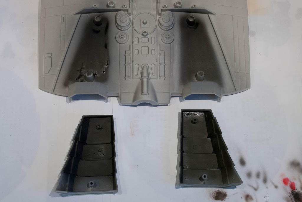
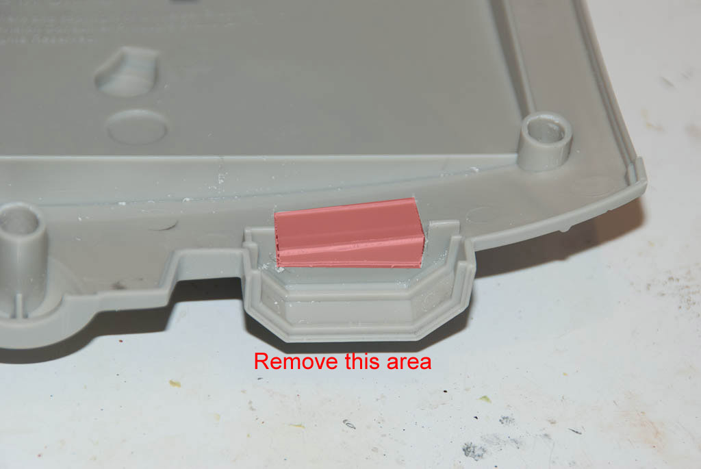
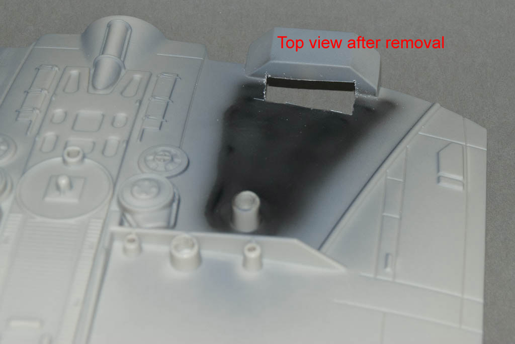
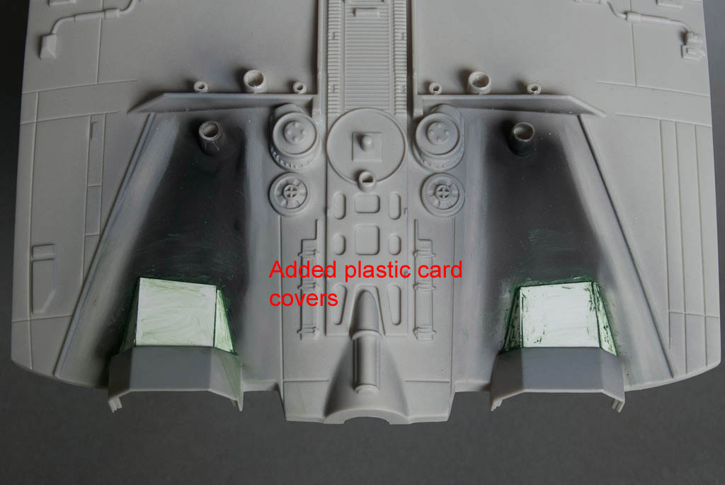
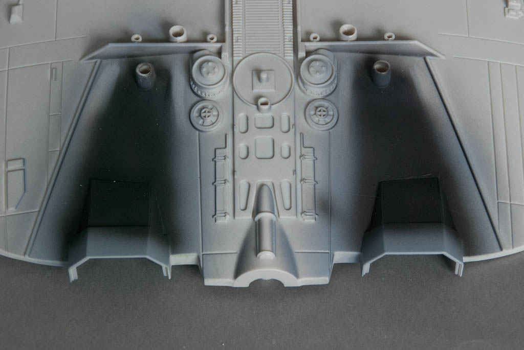
I started mocking up a 4 LED arrangement for the engines to test for alignment and dispersal and it was only then it actually clicked that the top half of the engine ‘tube’ does not continue into the body as it does on the Monogram kit. It’s screamingly obvious when you look at it, but I just failed to notice. Because the lights are to be mounted deeper inside the fuselage, this needs some modification to prevent the light being blocked. So it was out with the razor saw to remove a section of the moulding and then a new inner cover was made from sheet styrene – you don’t see this bit, it’s just to prevent light from leaking out of the louvered covers. This was also painted black for completeness. The mounting peg at the read of each faring also had to be removed, but the remaining one is more than adequate for locating the pieces when the are glued down.
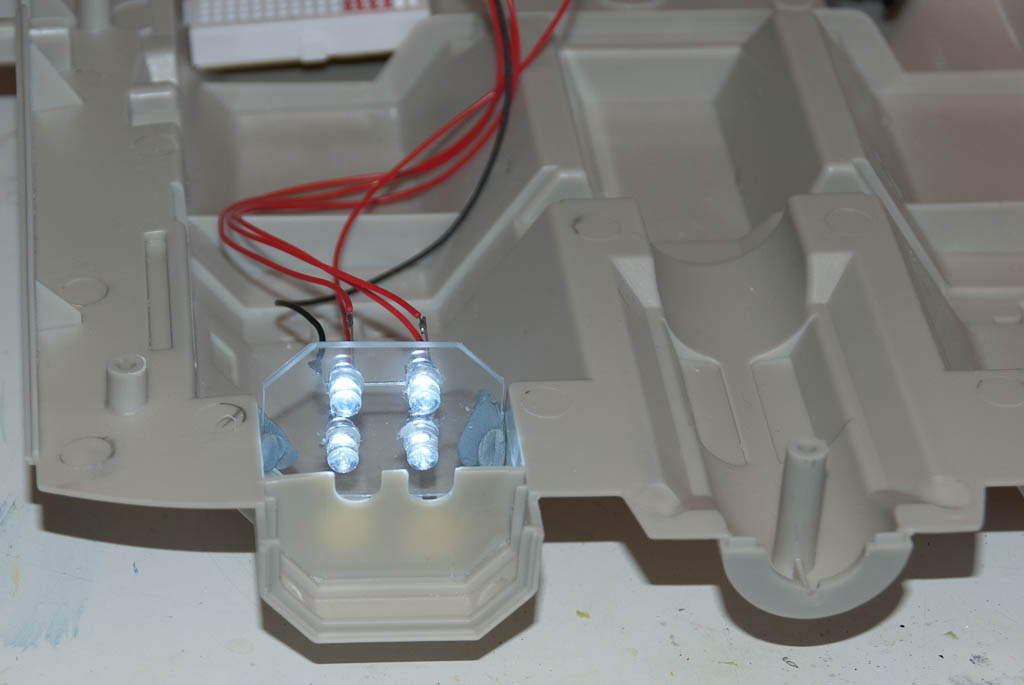

The position of the LEDs and the shape of the PCB were finalised and send off for production.
The inside of the engine tubes were given a coat of primer to help with light blocking – another coat may be needed, but the majority of the light is focussed straight out so that may be good enough.

Moving round to the front, 3mm holes were drilled into the corners of the front bulkhead detail (29) to accommodate 3mm LEDs for the headlights. In addition, the area directly behind these holes in the corresponding forward cabin part (10) was opened up to allow space for the back of the LEDs. Finally another hole in the back of each arm of part 10 was made for the headlight wiring to exit and be connected to the electronics.

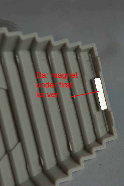
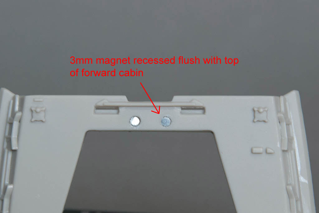
For the cockpit hatch, a small 3x3x12 magnet (I just happened to have lying around) was glued in under the front louver. Two 3mm dia x 2mm round magnets were recessed into the top of part 10 so that they lined up with the magnet in the hatch. This combination holds the hatch in place securely yet it can still be removed.
Very nice work. I just picked this up at WF. Will follow along.