Using Printer Resin as Filler

For decades I’ve been looking for an “easy” way to repair pinholes, air bubble defects and hairline gaps in resin kits. My usual filler choice is a 2 part epoxy like Miliput or MagiSculpt which usually works well for larger defects, but can be a real bind to use on tiny but still very visible issues. You can sit there and poke it into bubble holes but sometimes it can be hard to get it to stay in place without a lot of pressure, which usually ends up with it not completely filling the hole, or being distorted some how and requiring another application once the initial one has cured. This process can take hours to complete. It’s also hard to get very thin layers to adhere well to hairline defects where there just isn’t enough surface for the putty to stick to.

I’ve tired other types of more liquid fillers, but they all come with drawbacks – shrinkage is common in many – which again requires re-application, and some of the water based ones like using acrylic paste or Perfect Plastic Putty can give good initial effects but completely disintegrate if you need to wet-sand the area. Also the different hardness of the fillers can have an effect when areas are sanded – if there is a big difference then you can end up with an uneven surface as one component is eroded faster than the other. CA glue is interesting filler as it is relatively liquid yet can be hardened very quickly with kicker. But once fully cured it is significantly harder than urethane ‘kit’ resin.

A few years ago, UV-cure glue started to become readily available. I’d thought about trying this for modelling purposes but never actually tried it – to be honest I was a bit put off by some of the toxicity warnings on the packet of one I looked at…

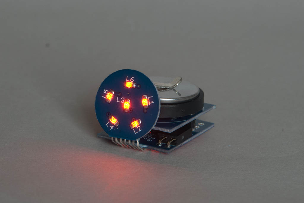
Fast forward a few years. The 3d Printing revolution is in full swing and I’ve owned both a “hot melt” FDM printer and a UV cure resin printer for some time. But until now I’d never made the mental connection between the UV glue products and the bottles of UV cure resin that are now sitting on my shelf. Eventually a light-bulb comes on – this is a type of resin that has very similar properties to urethane. It’s fairly liquid in an uncured state, but small amounts can be fully cured with little more than 20-30 seconds under a UV LED torch.

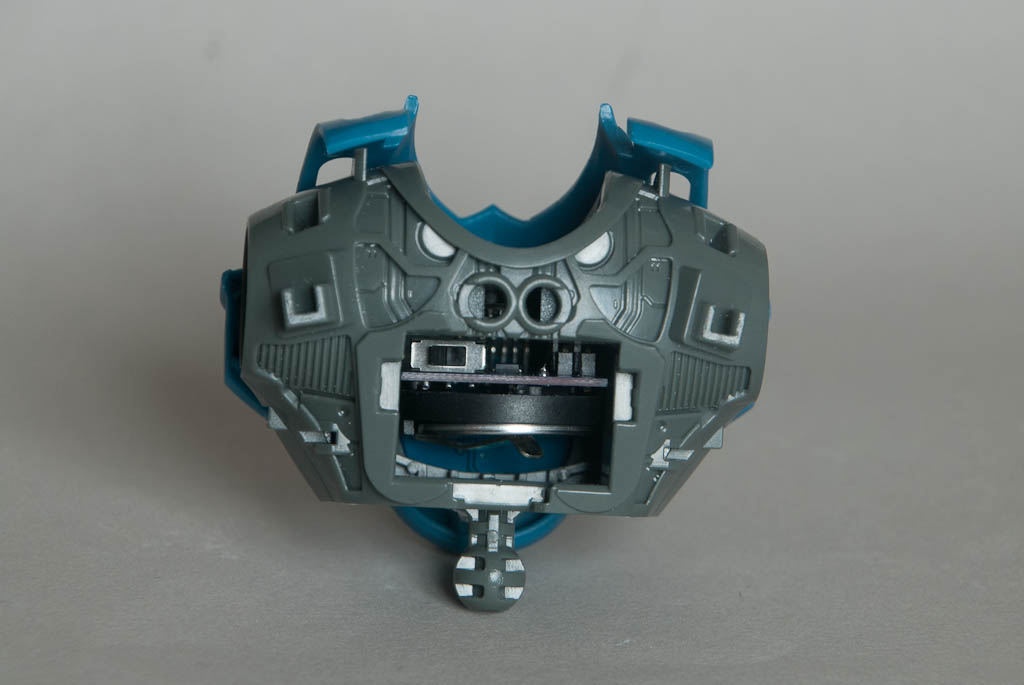
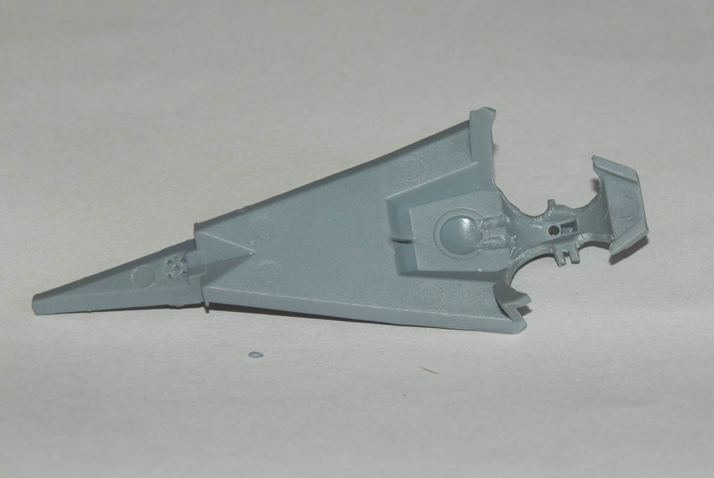
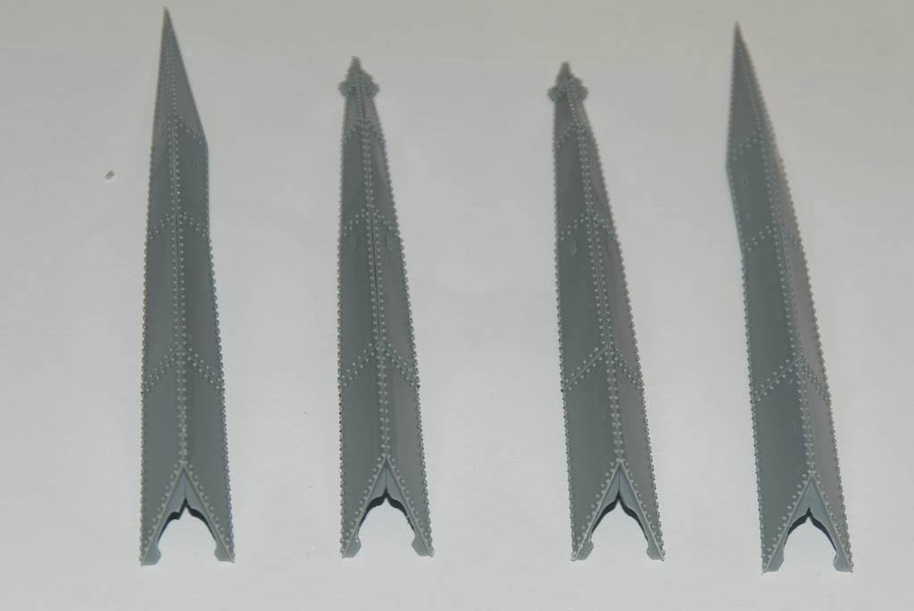
I chose one of the worst still-unbuilt kits in my collection – something I’ve had for around 20 years and has remained unassembled due to the utterly terrible quality of the casting. It’s a Mars Attacks Martian soldier – reportedly cast from one of the original maquettes used while the film was being developed. I can’t even remember where I got it from, other than somewhere over the internet in the very early days. The only reason I’ve still got it is it cost me an awful lot of money – money I would never have parted with if I’d know about the quality in advance. Caveat Emptor!

Every now and then I have dug this out of the back of the cupboard and had a go at filling a few more air bubbles with whatever new method I’ve been trying, but it’s always been a slog. But now was the time to get it out again and have an experiment with this latest technique.

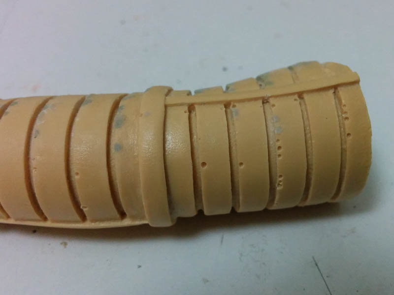
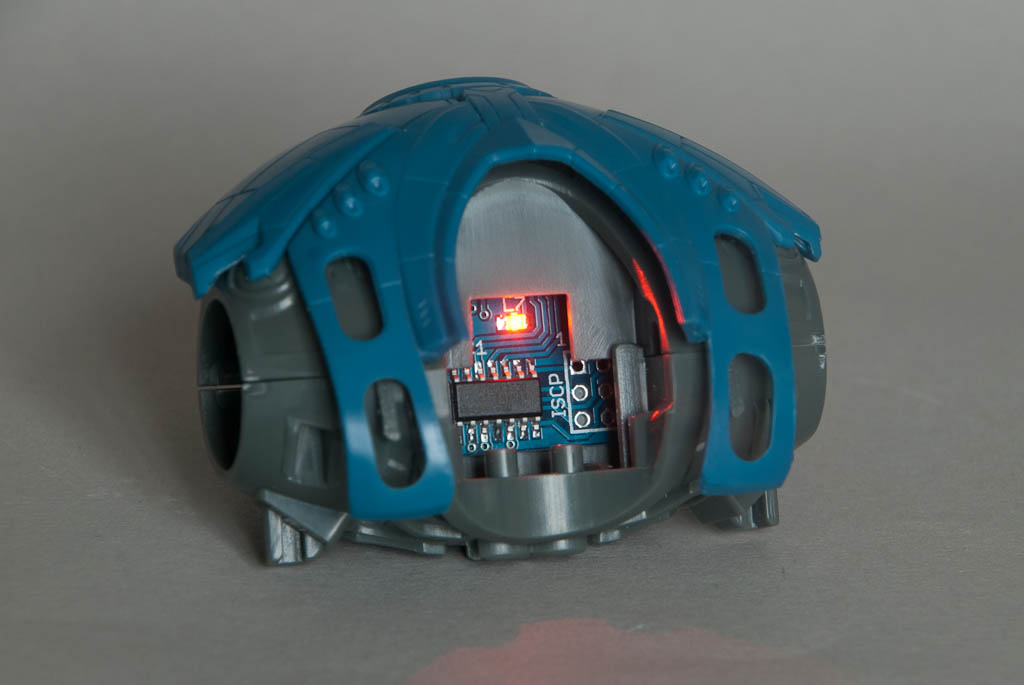
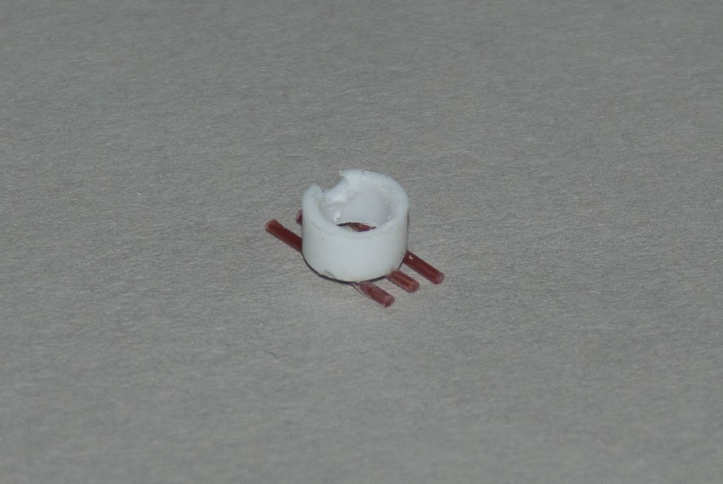
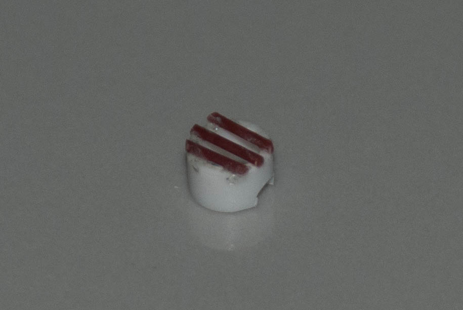
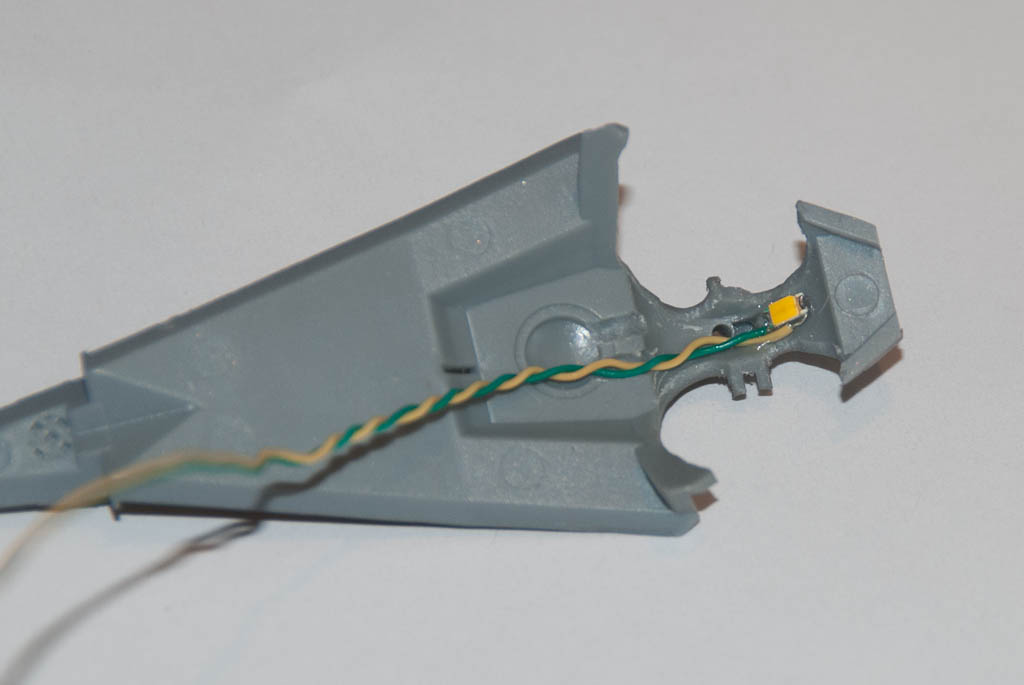
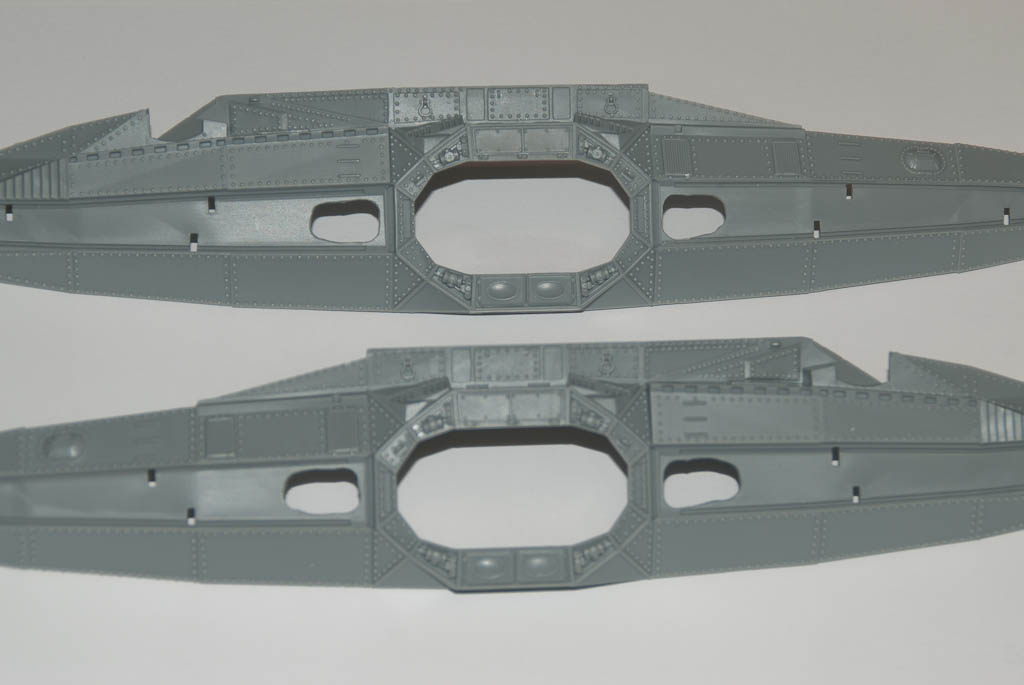
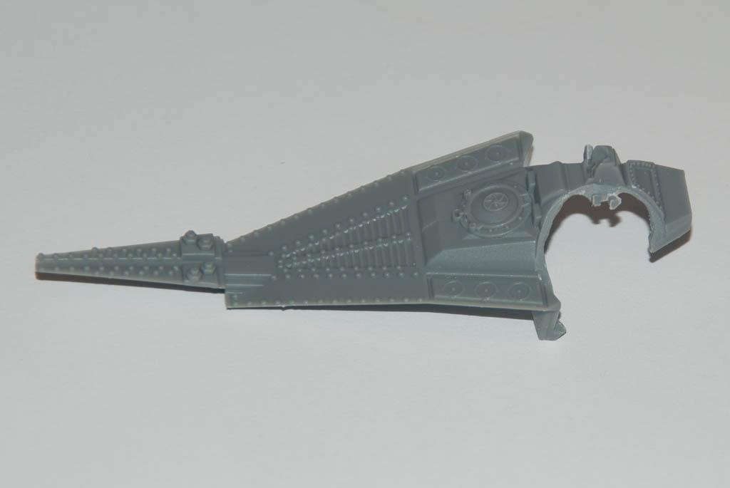
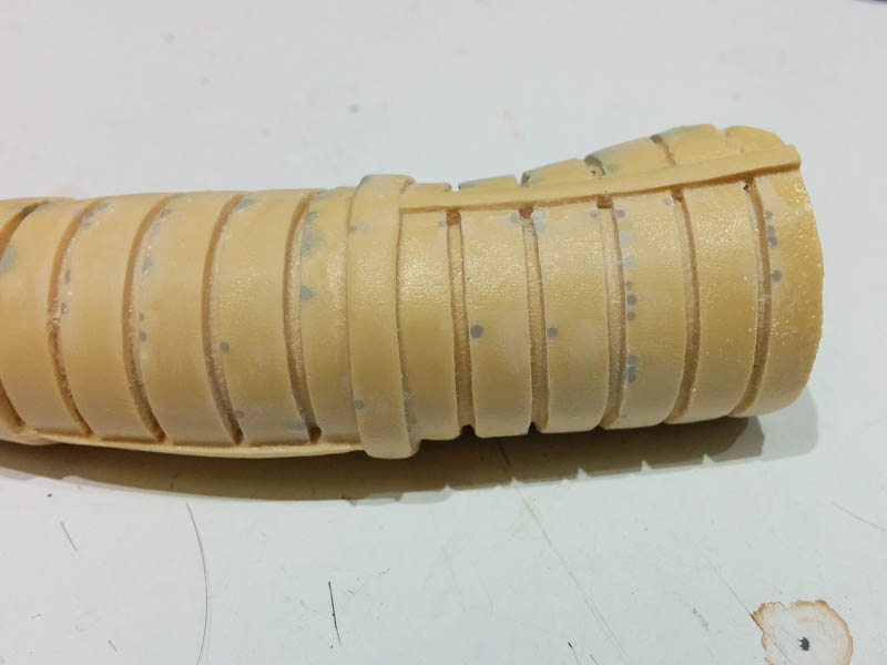
Here’s a typical flawed area – There are many air bubbles along the ribs of the spacesuit. You can see where some of these have been tackled with epoxy putty in years gone by, with varying success. Using a very small drill bit – probably around.7mm I actually made some of the smallest holes much “worse” by drilling them out some more. What you actually have is a larger bubble below the surface with only the very top open. It’s actually much easier to fill the bigger holes than the smaller ones, as odd as that may sound.

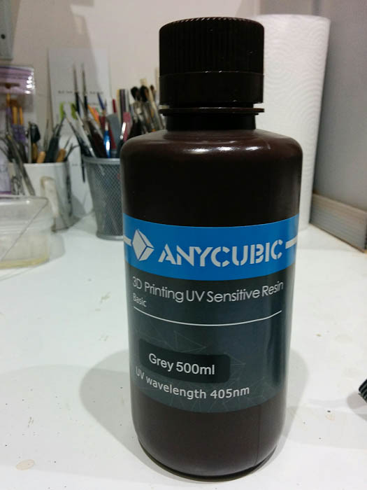
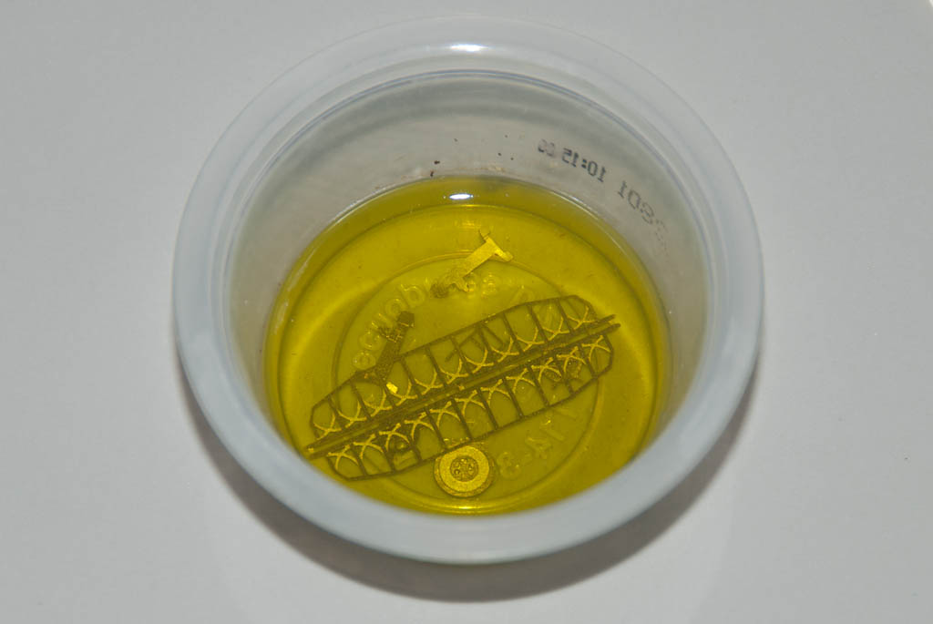
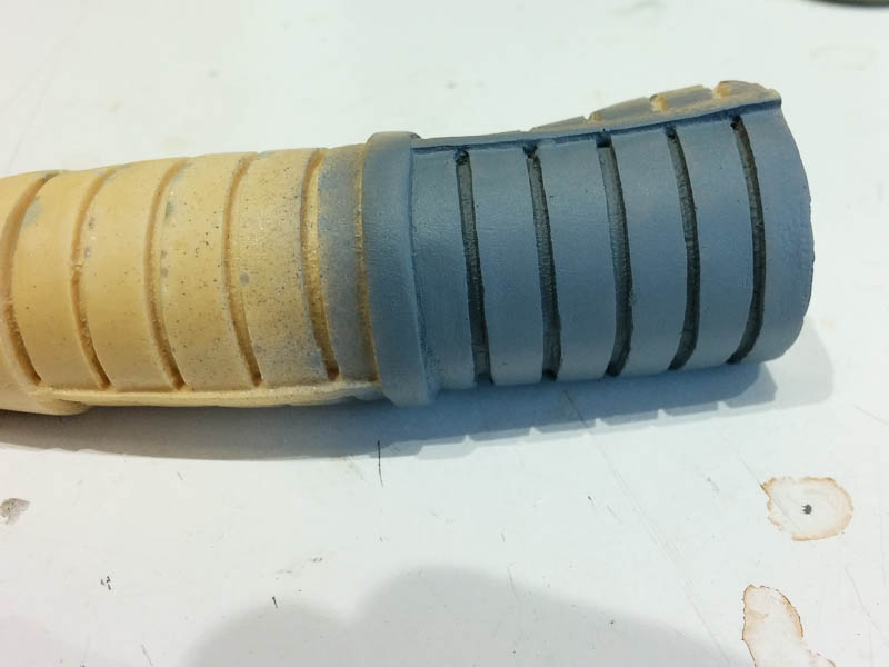
The grey resin I use with my Anycubic Photon printer. The resin is more expensive than 2-part urethane, but the prices have fallen dramatically over the last year or so as demand drives supply.

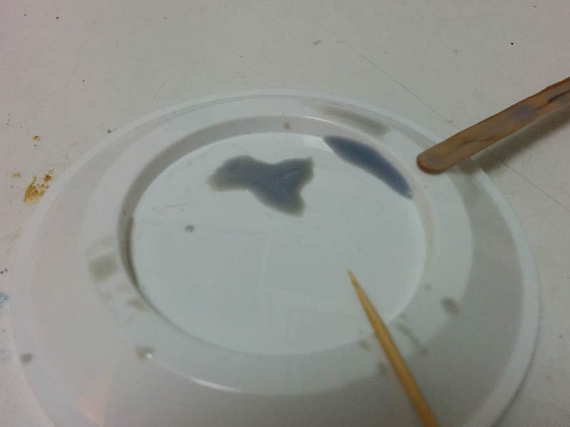
I dribbled a bit of resin out into a plastic lid for ease of use. You only need a tiny bit at a time. Since the resin is UV sensitive you need to work away from bright sunlight – in the UK winter, it will happily stay uncured on my workbench for several days!

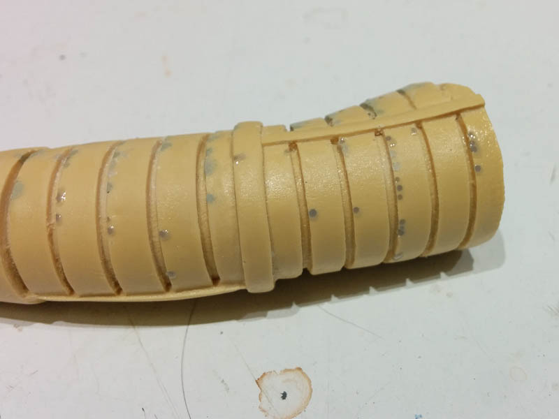
Using a toothpick, I filled each pinhole with resin, leaving the surface just slightly proud. It flows readily into the hole if the air inside can escape – this is the reason for making the smaller holes a bit bigger.

The resin was cured by shining a UV torch (eBay or your favourite online emporium. You need one with a 405nm wavelength to work with the resin) on each area for 30 seconds.

You can now sand the excess resin back down for a completely smooth and flawless finish. If you’ve underfilled the hole slightly, just apply a drop more, re-cure and re sand.

A quick shot of primer, and we’re looking in a much better state!

The same process works for seams and mold lines – just trickle a bead of resin along the area with the cocktail stick, cure and sand.

Larger holes and defects can be filled by repeated application – because the resin is fairly liquid it won’t hold shape on its own, so you need to build it up in layers. Also the thicker the resin, the more cure time you will need, so it’s better to cure in thin layers too.

Overall I was astounded how easy the process was. I sat and processed 50+ holes to a point where they would be ready for paint in about 15 mins. That would have taken a considerable time to do with Miliput, and you’d still have to wait for several more hours for it to cure before sanding and checking. Then comes the inevitable rework, taking even more hours.

So what’s the catch? There must be a catch right? Yes, there’s a catch.

The photo resin in its uncured state is pretty unpleasant stuff. It’s generally considered to be pretty toxic and you need to take safety precautions when using it. At the very least you need to wear latex/vinyl gloves because you don’t want to get it on your skin. Eye protection is also recommended in case of splashes when handling. It can be pretty smelly too so an adequately ventilated workspace is required, although the smell varies between different resins, and the amount being used for hole filling is nothing like having a vat-full exposed during a many hour 3D print, which is the normal mode of use. There are also on-going developments with safer resins, based on soy of all things which are supposed to be non-toxic but I think the jury is still out on validating those claims. No-one is lining up to be the first to drink a bottle to find out*

Having been so impressed which my experiments, I’m now keen to try it out in anger, but will have to wait as I don’t currently have any kits at the clean-up stage. This won’t replace other types of filler completely – you’ll still need putty for rebuilding texture and larger modifications, but I can see it becoming an essential and permanent part of my model-building arsenal.

I was lucky in that I already have the resin as part of the 3D printer toolset. But you can buy smaller bottles of resin on their own (250ml for around $20) in a variety of colours including translucent and completely clear which itself opens up a host of new possibilities for repairing clear parts. My next test is how well it woks as a styrene filler – I’m not sure how the two might stick together, but if there is a strong bond then it may be just as useful for styrene kits too.

* Legal disclaimer. Do not drink a bottle of any resin, under any circumstances!

Lighting Module for Max Factory Gypsy Danger

Yet another lighting project on the go – this time for the new Pacific Rim Gypsy Danger kit from Max Factory / Plamax.

The kit does come with a small lighting module, but this is rather disappointing. It uses a single LED to illuminate both the chest turbine, and, through a rather convoluted arrangement of clear pieces, the visor too. One big advantage is that the kit has been designed to allow access to this module for battery replacement once assembled.

I wanted to have a turbine effect more like as seen in the film, so have designed a system that uses a ring of LEDs (and one in the middle) that can be animated in a rotating configuration. Space is very tight, so I have split the design up into 3 pieces – An LED board that sits behind the clear turbine cover, a main driver board that fits into the main chest cavity and which provides the animation for the LEDs and also contains an additional LED to shine directly up into the head to illuminate the visor better, and finally a power board containing the battery and on-of switch. The power board sits under the main board but can be easily unplugged and removed from the model to facilitate changing of the battery.

Bandai Pocket Model TIE Fighter Panel Masks

A recent addition to Bandai’s Pocket Model range is a twin pack of a TIE Fighter and Darth Vader’s TIE-Advanced. These would be very easy builds were it not for having to mask all the solar panel segments. After briefly experimenting with tape, I gave up and got the digital callipers out to measure up the TIEs panel and make some mask of my own. Thankfully there are only 2 different shapes once you flip one of them. These were drafted up in Inkscape, checked, adjusted, and then duplicated. I’ve got 2 sets of the kits so that I could have the full Vader and 2 escorts as the tilt stand allows for, so in total I needed to mask 6 segments on 2 sides of 4 panels – 48 masks in total. I also added a few spares just in case.

These were arranged into a single sheet of A4 for convenience and printed out on standard photocopy paper. You could use higher quality paper but I didn’t really find it necessary. A fresh blade in the craft knife was used to cut out all the masks to avoid any ragged edges. After spraying the TIE panels black, each mask was glued in place with liquid latex (Humbrol Maskol in my case) – just a series of small blobs around the periphery of the panel segment was enough to hold the paper down, but not enough to cause it to wrinkle up. Then using a fairly low pressure, the grey frame colour was airbrushed between the panels, taking care to keep the airbrush at 90 degrees to the panel to minimise any spray bleed underneath the mask.

The results were more than satisfactory, and by the final panel didn’t take long to apply and paint at all.

For anyone else that wants to try this, the masks are available below – free of charge – in either A4 or US Letter paper format.

TIE Masks – A4 (PDF)

TIE Masks – US Letter (PDF)

Zvezda/Revell Star Destroyer Lighting Module

Whilst waiting for the Zvezda Star Destroyer to become available through Revell in Europe, I have started putting together a speculative lighting controller board.

This features a flickering effect for the 3 main engines and the 4 auxiliary engines. It also provides 12 additional static (non flickering) LEDs to provide light for the windows via fibre optic strands.

The board has been designed primarily for battery power and has a total current draw of around 60mA – which should give may hours of operation on a set of 3 AAs. Alternatively there is also an on-board voltage regulator that can be fed from a 7-12v wall adaptor.

This test build features cool white LEDs for the engines and warm white for the windows

Bandai Star Destroyer Part 3

<< Part 2

Everything is just about there. The fibre marries up with the central LED much better now. I’ve added some short lengths of 1.5mm fibre at the rear of the 3 main engines to act as light pipes – this gives a much better effect inside the engine bell than just having a hole.

The last thing to resolve is the wires for the battery supply. I want these to run down through the stand, but it’s just a bit too small to get 2 bits of my smallest stranded cable down. For now I’ve used 2 bits of solid core wire wrap wire – these are plenty small enough, but will not survive much manhandling or moving of the ball & socket joint. Need to come up with a better solution…

For now here’s some beauty shots. The ship was primed in a just off-white colour and then given a wash of Concrete Flory Wash. Once dry, the excess was wiped away with a slightly damp sponge & that’s it. I’ve used a focusable LED torch several meters away as a slight source in an attempt to simulate the parallel light of a far-distant sun…

Bandai Star Destroyer Part 2

<< Part 1

Small amount of progress before Christmas got in the way. After trying to use 0.5mm fibre for the smaller engines I gave up due to the problems with bending them up to the LED – they were just too stiff over such a small length. So I downsized to 0.35mm which works better but still had some issues with the off-centre LED placement, so I have decided to take the hit and do a PCB revision with a few tweaks:

  •  Small engine LED moved to centre and brought back a few mm to help with clearance around the fuselage top.
  •  Larger slots at back of PCB to aid routing lower fibres up to top of PCB.
  •  Increase clearance around side holes for a better fit.
  •  Rework main engine LED pads to allow a different type of SMD package, and remove unused through-hole pads.

Just waiting for the new boards to arrive, but here’s the old one in action with the fibre.

dsc_9219 dsc_9218

Time passes..

The new boards have arrived, so quickly made one up for comparison. Having the engine LED in the centre is much better, and I was able to go back to the 0.5mm fibre for the small engines. Everything also fits better inside, and the top of the Destroyer fits on with ease.

dsc_9225 dsc_9227

dsc_9229 dsc_9230

Part 3 >>

Bandai Star Destroyer Lighting Module

I recently acquired Bandai’s new “palm size” Star Destroyer kit – A great little kit!. There’s a tiny bit of space inside so I thought I’d have a go at doing a module for lighting the engines.

There are 3 LEDs that line up directly with the main engines, and a fourth to be used as a source for 4 bits of fibre optic to light the intermediary engines. All of these LEDs are programmed to produce a flicker effect. A final static (no flicker) LED can be used to feed fibre to light windows in the Destroyer, although I’m not sure I’m going to bother with that. Too fiddly!

All the engines need carefully drilling out. I used 1.5mm for the main engines and will be fitting 0.5mm fibre to the intermediaries.

Power wires come off the bottom of the board and are designed to feed out through the stand mount – again these need to be drilled out to accommodate.

So far so good.

dsc_9212

Main engines, rear view

dsc_9215

Part 2 >>

Pegasus Nautilus Part 3

<< Part 2

The original plan was to use 3mm LEDs in the spotlight and wheelhouse, but after playing around for a while I concluded they were going to be too big. The solution was to use a couple more surface mount LEDs but soldered onto wires to make super small freestanding lights. Using 1206 sized packages it’s still possible to manually solder single core wire-wrap wire onto the contacts with a fine point soldering iron bit. Holding the LED in some reverse action tweezers (the sort that grip til you squeeze them) really helps for this bit.
Once the wires were soldered, a small blob of clear 5-min epoxy was used to bind everything together securely.

DSC_8684 DSC_8685
I decided to scratch-build a new searchlight from a 2mm length of 3mm I/D styrene tube. The LED sits at the back of this perfectly after a small notch was filed in the back end for the wires. The grille on the front of the searchlight was replicated by gluing 3 very thin styrene rods across the front end of the tube. Once the glue had hardened, the excess rod was trimmed off and the edges sanded flush with the tube.
DSC_8679 DSC_8682 DSC_8720
After priming, the inside was painted silver to help reflect the light. The LED was glued in place with more 5-min epoxy and once set, a small cone of Miliput was added to the back to match the original kit part.
DSC_8727 DSC_8728 DSC_8729
The hole where the searchlight mounts on the wheelhouse roof was drilled through so the wires can pass inside when the light is attached.
A second wired LED was glued onto the ceiling of the wheelhouse just a bit further back than where the searchlight wires will come in. The wiring for both was then routed forwards along the ceiling and into 2 groves cut into the ceiling where the wall of the photoetch wheelhouse assembly will fit.
DSC_8732 DSC_8733

Pegasus Nautilus Part 2

<< Part 1

One of the problems I’ve found with photo etch is that paint doesn’t stick to it very well due to the very shiny finish. Ideally you should use an etching primer that bites into the surface before curing but I didn’t have any of that around so I had a go at replicating the process instead.

I had some Ferric Chloride left over from etching some prototype PCBs many years ago, so I used a few drops to make a much much weaker solution than would normally be used – all I wanted was to cut into the metal surface microscopically, not dissolve it away.

After a 30 minute soak, then good wash, the parts had a nice tarnished and very matt surface. This allows regular primer to stick very well indeed.

DSC_8597 DSC_8600 DSC_8616

Painting of the lounge proceeded. I went for a fairly basic colour scheme, light gray/green for the walls, oily steel for the floor plates and dark brown for the woodwork, with red leather covering on the sofa & chair. The books were blocked out in a range of colours with just the odd one out of place to jumble things up. I had to keep telling myself most of this will not be visible!

DSC_8601 DSC_8602

A quick test with the lights overhead verified that some of it will be visible – although there is still the main window panels to go in yet which will restrict sight further. I don’t think I will use the PE storm shutters on the windows.

DSC_8611 DSC_8614 DSC_8615

I also shot a short video showing some typical lighting sequences – these have been shortened for the video, I will probably leave a minute or so between changes in the final model.

Part 3 >>

Pegasus Nautilus Lighting Module – Part 1

I’ve started work on an animated lighting module for the Pegasus Nautilus submarine. This kit features a detailed interior, which is improved even further by the ParaGrafix photo-etch detail set. This includes an additional interior for the forward wheelhouse as well as extra details for the main lounge/observation room. The ceiling of the observation room features 16 lighting panels, so I decided the easiest way of tackling this project was to design a module that had 16 LEDs mounted on the bottom that line up with these panels. After opening up the panels, the PCB will sit on top and shine through into the observation room with no messy wires. Part of the PE set includes some nice perforated panel covers which will improve the overall lighting effect.

Apart from the ceiling lights, there are 4 exterior spotlights, two on each side of the hull at either side of the big observation windows – obviously designed to illuminate the murkey depths. Finally an interior light is needed to illuminate the wheelhouse and one more for the searchlight mounted on the top of the vessel.

There’s not much the lights really “do” but rather than just be static I decided to go with a fairly simple system that turns the lights on and off in various sequences.
A quick circuit was drawn up based around an Atmel ATTiny84 micro controller – this has enough outputs to drive the ceiling lights as 4 strips of 4, 2 pairs of spotlights, port and starboard, the wheelhouse, and the searchlight. It’s small enough to fit everything easily on a PCB no bigger than the top of the observation room.

The four spotlights protrude from the ends of triangular wedge shaped strips that attach to the sides of the hull. I started off gluing the halves of each wedge together. A small end cap holds the clear piece representing the spotlight window. Normally this clear part must be attached before the end cap is secured in place due to the way it is partially covered by an alignment lip on each side. I wanted to keep the clear parts of until initial painting was completed, so I removed the lip overlap from the end of the wedge to allow the window to be dropped in later.
DSC_8562 DSC_8563

A 5mm LED fits quite snugly into the back of the window. The LED and wires will need to be fed through from the inside of the hull, so I opened up a hole in the side of the hull roughly behind where each LED will sit.

DSC_8561

In order to see into the wheelhouse though the top windows, it’s necessary to open up the area that normally blanks these off from part C3.

DSC_8564 DSC_8565

Opening up the light panels in the ceiling is quite a tedious job. I started by drilling 2mm holes around the inside of each panel, then cutting out the remaining plastic between the holes with a knife. The inside of the panel was then filed into a clean rectangle. You don’t have to be too precise here since the PE panel cover will hide any untidiness.

DSC_8566

When fitting the PE crossbeam details, pay attention to the fact one side is about 1mm shorter to the other side (due to how the pipes of the organ on the back wall are arranged). Whilst doing a test fit after this stage I discovered a much larger issue – the detail end-pieces on the longer beam also foul the top of the bookcase on the other wall! There is no mention of this in the PE instructions at all. I had to file down the points on the end of the beam, and also file a 2mm wide slot into the top of the bookcase to get the ceiling panel to fit properly into the side wall lugs.

DSC_8567 DSC_8569

Attaching the PE light panel covers is quite fiddly. I found the best way was to put a couple of spots of CA on the raised lip of the panel hole, and then pick the covers up with needle-nose tweezers through a couple of the holes in the PE and then lower into place and hold until the glue grabbed. With the tweezers in the holes it’s relatively easy to ensure each panel is correctly positioned and square.

DSC_8574

A PCB was draughted up and sent off for manufacture. I chose to go with a white solder resist coating rather than the traditional green as this will help spread the light inside each of the lighting panels. After about 2 weeks, a parcel of boards arrived and I set to work assembling one. With the exception of the LEDs for the spotlights, searchlight and wheelhouse, all the components are surface-mount types. The 16 observation room lights and their series resistors are on the bottom and everything else is on the top. Connectors were added for all the other LEDs – not really necessary but it does mean the board can be completely removed during assembly if necessary.

DSC_8580 DSC_8581

Once assembled, a small bit of code was put together to fade the lights up and down in a semi-random sequence and uploaded to the microcontroller. This will probably be tweaked a bit as the project progresses.

DSC_8584 DSC_8590 DSC_8596

Part 2 >>