Bandai Pocket Model TIE Fighter Panel Masks

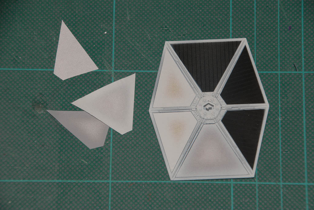
A recent addition to Bandai’s Pocket Model range is a twin pack of a TIE Fighter and Darth Vader’s TIE-Advanced. These would be very easy builds were it not for having to mask all the solar panel segments. After briefly experimenting with tape, I gave up and got the digital callipers out to measure up the TIEs panel and make some mask of my own. Thankfully there are only 2 different shapes once you flip one of them. These were drafted up in Inkscape, checked, adjusted, and then duplicated. I’ve got 2 sets of the kits so that I could have the full Vader and 2 escorts as the tilt stand allows for, so in total I needed to mask 6 segments on 2 sides of 4 panels – 48 masks in total. I also added a few spares just in case.

These were arranged into a single sheet of A4 for convenience and printed out on standard photocopy paper. You could use higher quality paper but I didn’t really find it necessary. A fresh blade in the craft knife was used to cut out all the masks to avoid any ragged edges. After spraying the TIE panels black, each mask was glued in place with liquid latex (Humbrol Maskol in my case) – just a series of small blobs around the periphery of the panel segment was enough to hold the paper down, but not enough to cause it to wrinkle up. Then using a fairly low pressure, the grey frame colour was airbrushed between the panels, taking care to keep the airbrush at 90 degrees to the panel to minimise any spray bleed underneath the mask.

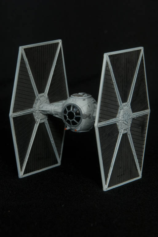
The results were more than satisfactory, and by the final panel didn’t take long to apply and paint at all.

For anyone else that wants to try this, the masks are available below – free of charge – in either A4 or US Letter paper format.

TIE Masks – A4 (PDF)

TIE Masks – US Letter (PDF)

Bandai Star Destroyer Part 3

<< Part 2

Everything is just about there. The fibre marries up with the central LED much better now. I’ve added some short lengths of 1.5mm fibre at the rear of the 3 main engines to act as light pipes – this gives a much better effect inside the engine bell than just having a hole.

The last thing to resolve is the wires for the battery supply. I want these to run down through the stand, but it’s just a bit too small to get 2 bits of my smallest stranded cable down. For now I’ve used 2 bits of solid core wire wrap wire – these are plenty small enough, but will not survive much manhandling or moving of the ball & socket joint. Need to come up with a better solution…

For now here’s some beauty shots. The ship was primed in a just off-white colour and then given a wash of Concrete Flory Wash. Once dry, the excess was wiped away with a slightly damp sponge & that’s it. I’ve used a focusable LED torch several meters away as a slight source in an attempt to simulate the parallel light of a far-distant sun…

Bandai Star Destroyer Part 2

<< Part 1

Small amount of progress before Christmas got in the way. After trying to use 0.5mm fibre for the smaller engines I gave up due to the problems with bending them up to the LED – they were just too stiff over such a small length. So I downsized to 0.35mm which works better but still had some issues with the off-centre LED placement, so I have decided to take the hit and do a PCB revision with a few tweaks:

  •  Small engine LED moved to centre and brought back a few mm to help with clearance around the fuselage top.
  •  Larger slots at back of PCB to aid routing lower fibres up to top of PCB.
  •  Increase clearance around side holes for a better fit.
  •  Rework main engine LED pads to allow a different type of SMD package, and remove unused through-hole pads.

Just waiting for the new boards to arrive, but here’s the old one in action with the fibre.

dsc_9219 dsc_9218

Time passes..

The new boards have arrived, so quickly made one up for comparison. Having the engine LED in the centre is much better, and I was able to go back to the 0.5mm fibre for the small engines. Everything also fits better inside, and the top of the Destroyer fits on with ease.

dsc_9225 dsc_9227

dsc_9229 dsc_9230

Part 3 >>

Bandai Star Destroyer Lighting Module

I recently acquired Bandai’s new “palm size” Star Destroyer kit – A great little kit!. There’s a tiny bit of space inside so I thought I’d have a go at doing a module for lighting the engines.

There are 3 LEDs that line up directly with the main engines, and a fourth to be used as a source for 4 bits of fibre optic to light the intermediary engines. All of these LEDs are programmed to produce a flicker effect. A final static (no flicker) LED can be used to feed fibre to light windows in the Destroyer, although I’m not sure I’m going to bother with that. Too fiddly!

All the engines need carefully drilling out. I used 1.5mm for the main engines and will be fitting 0.5mm fibre to the intermediaries.

Power wires come off the bottom of the board and are designed to feed out through the stand mount – again these need to be drilled out to accommodate.

So far so good.

dsc_9212

Main engines, rear view

dsc_9215

Part 2 >>