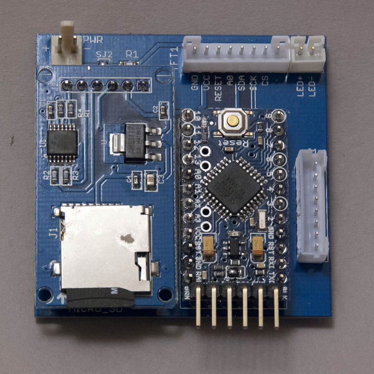
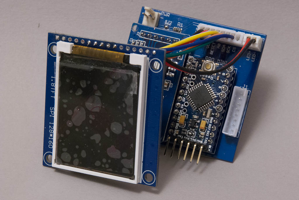
The original plan was to put together a PCB with a minimalist ATMEGA 328 circuit to ferry the images from the SD card to the display in an appropriate sequence, but after a bit of rooting around I found I could buy a complete Arduino Pro Mini clone from the far east (free shipping) for less than I could source the 328 MCU alone locally (with inevitable excessive shipping). So that’s what I did.
The new plan was to just connect the Pro Mini, SD and display with a rats-nest of wires but eventually I decided to put together a small motherboard that would house the Pro Mini and SD, and use a couple of JST PH connectors to wire up the display, and LEDS for the 2 “fluorescent” tube lights on the body, and for Gerty’s “eye”. These will be driven by additional I/O lines from the Pro Mini so that they can be controlled via the software rather than just being always on. This also allows the motherboard to be detached and removed from the body of the kit for software updates.
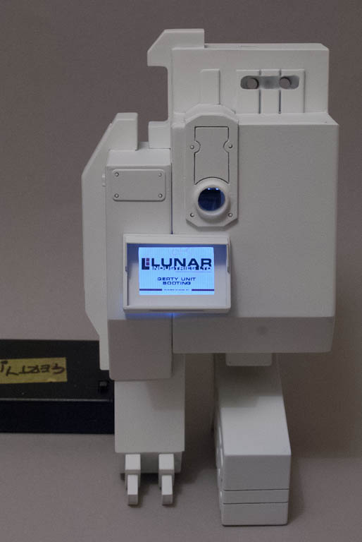
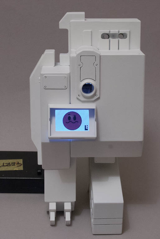
Getting the Display board into the right place has been a bit of a challenge, and has involved the addition of plastic mounting runners and guiding tabs to hold it securely. The bottom of the LCD has to protrude at exactly the right angle so that it mates with the bezel precisely once the bezel is inserted in place. I intend to leave the two halves of the body unattached, and held in place just with a couple of small neodymium magnets. This means that the bezel cannot be permanently fixed to the body either since it spans both halves.
After much fiddling & tweaking & fiddling & swearing, I’ve eventually managed to get everything in and staying in the right place!