Moebius have just released their 1/32nd ‘Studio Scale’ Cylon Raider kit from the original BGS series. For some reason this pancake has always been one of my favourite sci-fi ships. I still have a built-up Monogram version that was released in 1979 – one of the very few models that remains intact from my childhood that didn’t get blown up, burnt, broken or bashed into something else many many years ago!
 The first and obvious thing to note is the kit’s size! it’s about double that of the Monogram kit and looks very imposing. It’s much more accurate to the studio miniature, featuring recessed panel lines and more detail particularly around the nose, tail & engines.
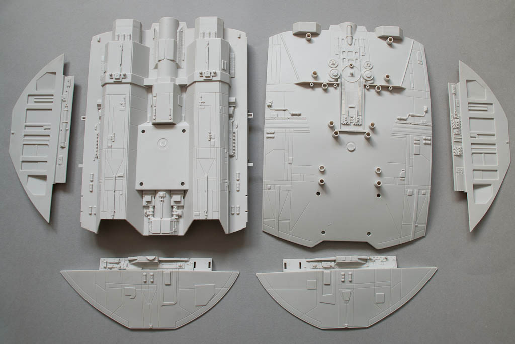
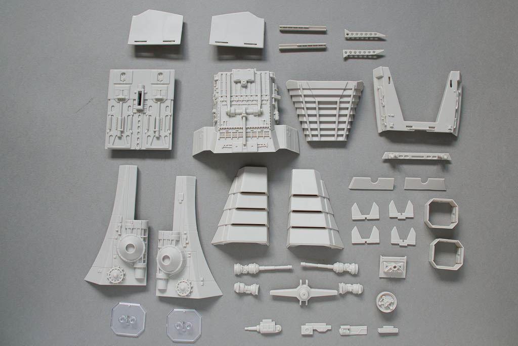
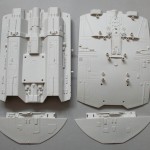
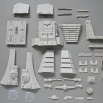 You get 49 pieces, including 2 clear engine inserts and a clear stand – a scaled up version of the regular Moebius BSG stand. Parts are generally moulded well although the detail is somewhat soft by modern standards – it’s certainly not up to Fine Molds standards, and even a Revell re-pop of the Monogram kit looks crisper.
There are a couple of small sinkholes at the front of the top fuselage that need filling but that’s it. Fit of the parts is pretty good with a few issues:
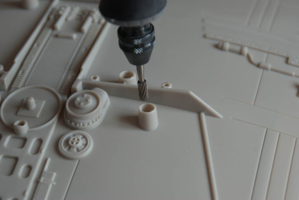
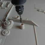 Many of the larger parts are secured by peg and socket arrangements – these are tight enough to hold the model together without glue but can actually prevent some of the parts mating together completely unless squeezed hard. Using a 4mm end mill in my Dremel, I enlarged the inside of each socket slightly and shortened the length of each peg. The pieces are now a looser fit but the seams are now flush without requiring force and ready for gluing.
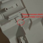 There are also some ejector pin defects on the back of some parts (eg the underside bottom plate that the stand fits into (part 12)) that can also prevent parts aligning correctly. These are easy to remove with the Dremel again or a bit of light sanding.
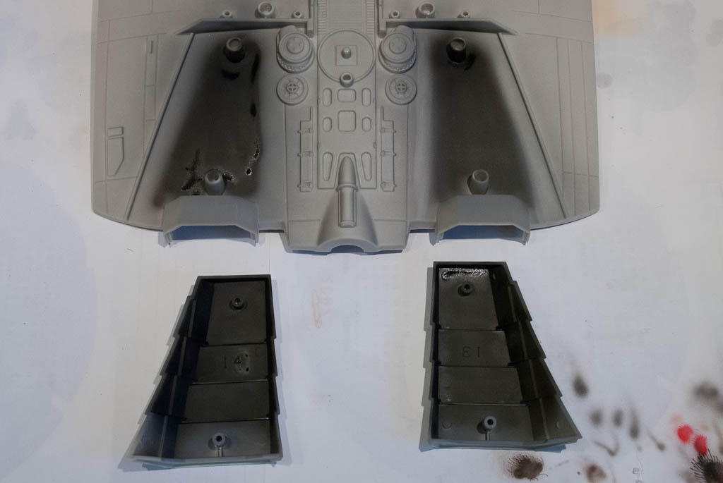
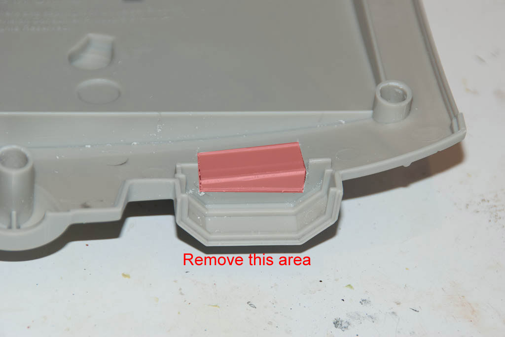
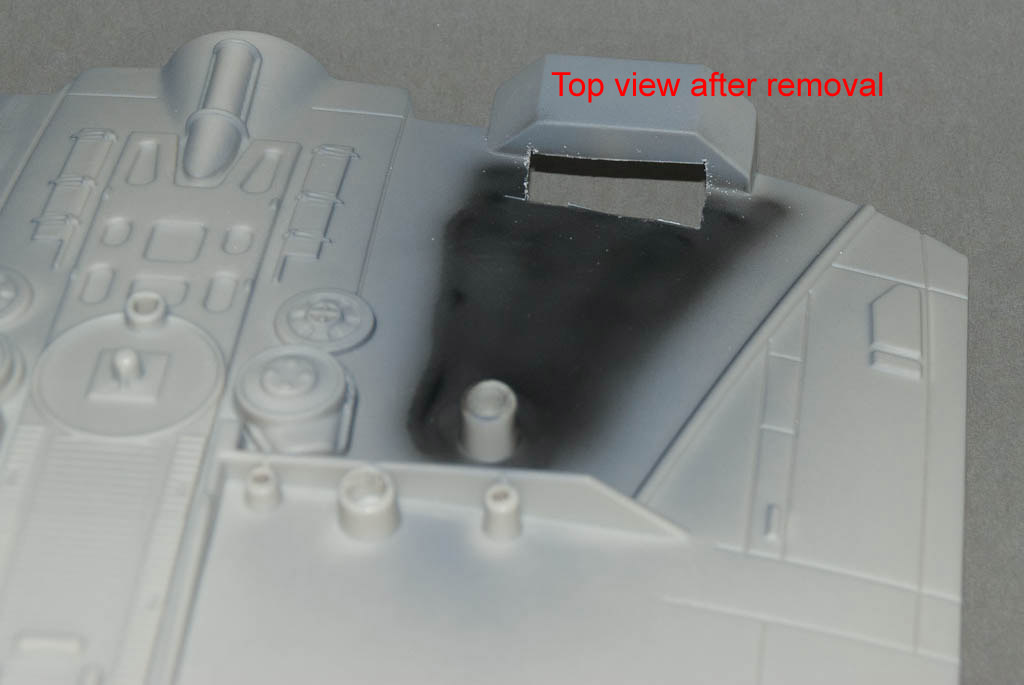
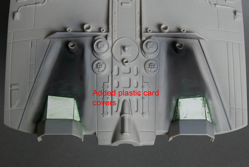
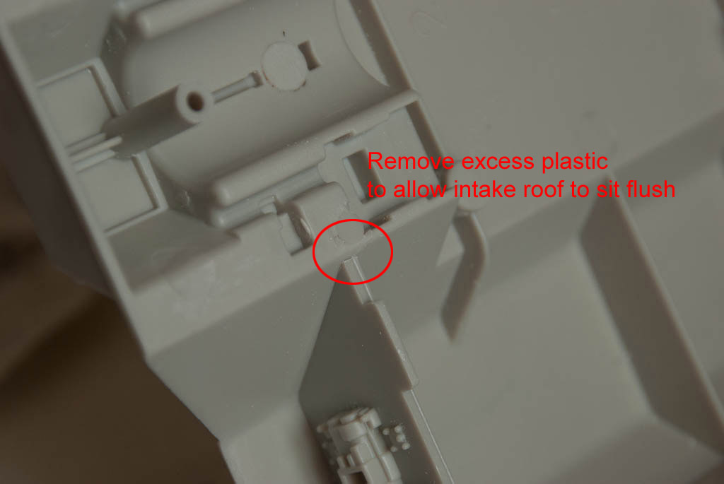
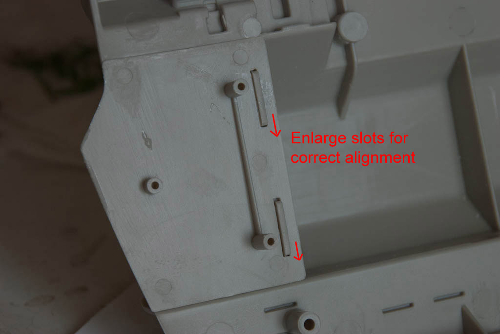
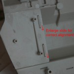 There are 2 areas where a part socket actually fouls the location of the underside intake roof covers (parts 17 and 19) – these need to be carefully sanded down for a correct fit. The long slots in these parts also need extending by a few mm to aid positioning.
It’s really worth dry fitting each part to ensure everything is as it should be before applying glue.
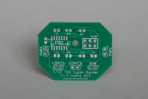
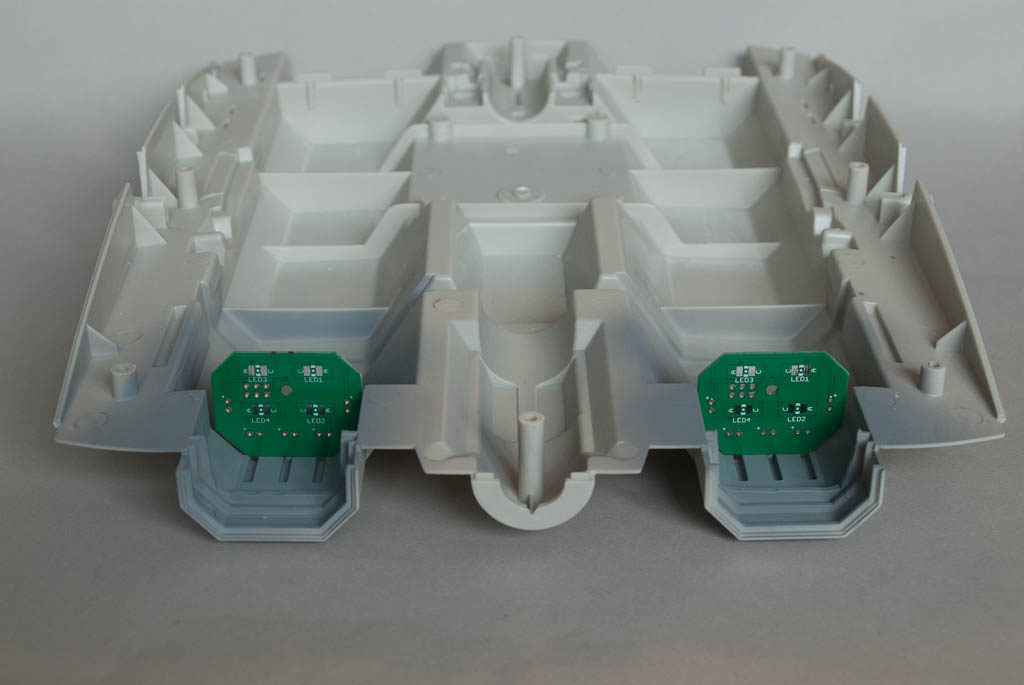
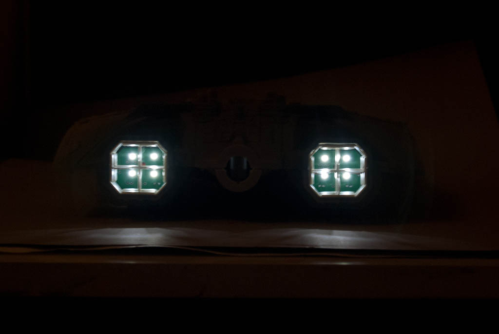
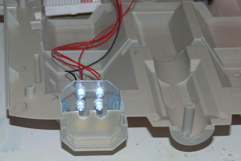
The engines each come with a clear backing piece with 2 5mm sockets moulded in that look like they are designed to allow a couple of 5mm LEDs to be dropped right in for a quick & easy lighting option. However a bit of experimentation shows that the design and position of the sockets (directly behind the exhaust vanes of the engine) mean that a large majority of the light is blocked or deflected.
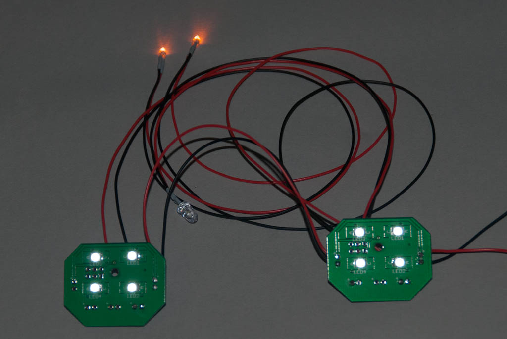
I had already started work developing a custom lighting set for the kit before it arrived – seeing the above implementation made me waver in my conviction for a short while before deciding to carry on with my original design which uses 4 LEDs per engine, one in each quadrant. They will also be microprocessor driven to provide a realistic flicker effect much like the module I did for the new series Raider.
Additional laser gun effects will be provided as well as hook-ups for the static headlights and underbelly lights (neither of which are featured in the kit but can be added easily).
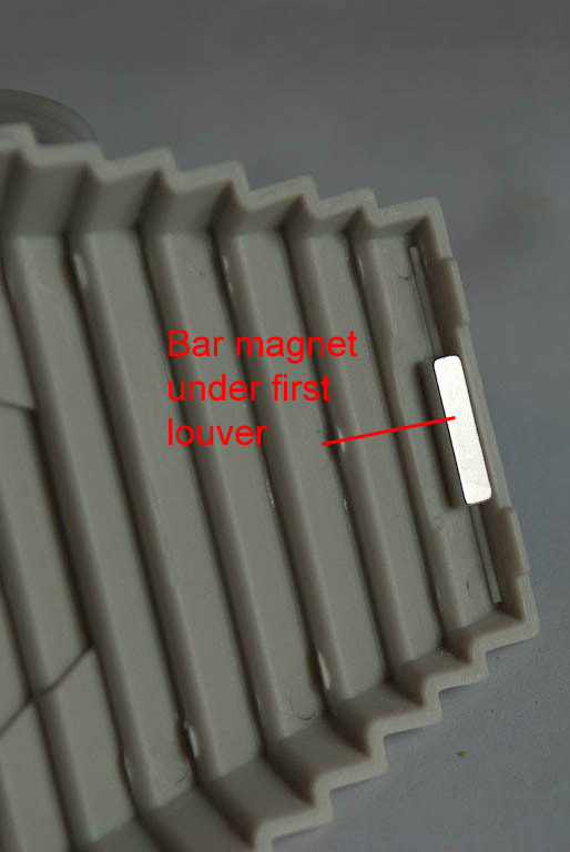
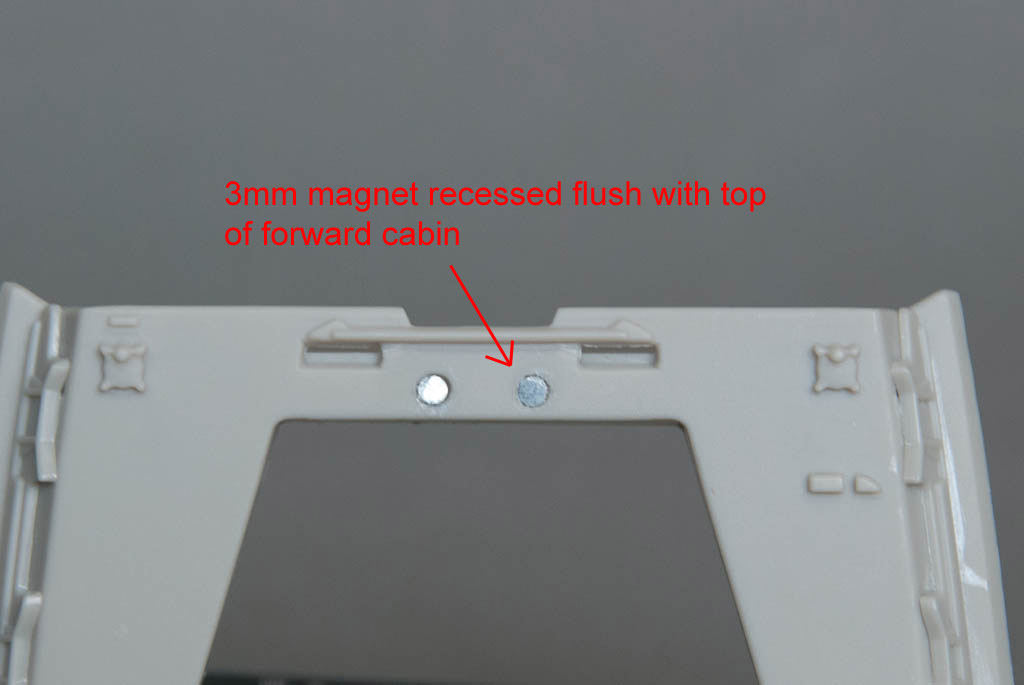
Thankfully this kit has plenty of space inside for a change! A 3AA battery pack will easily sit under the cockpit cover, which will be attached via magnets to make it removable for access.
>> Part 2