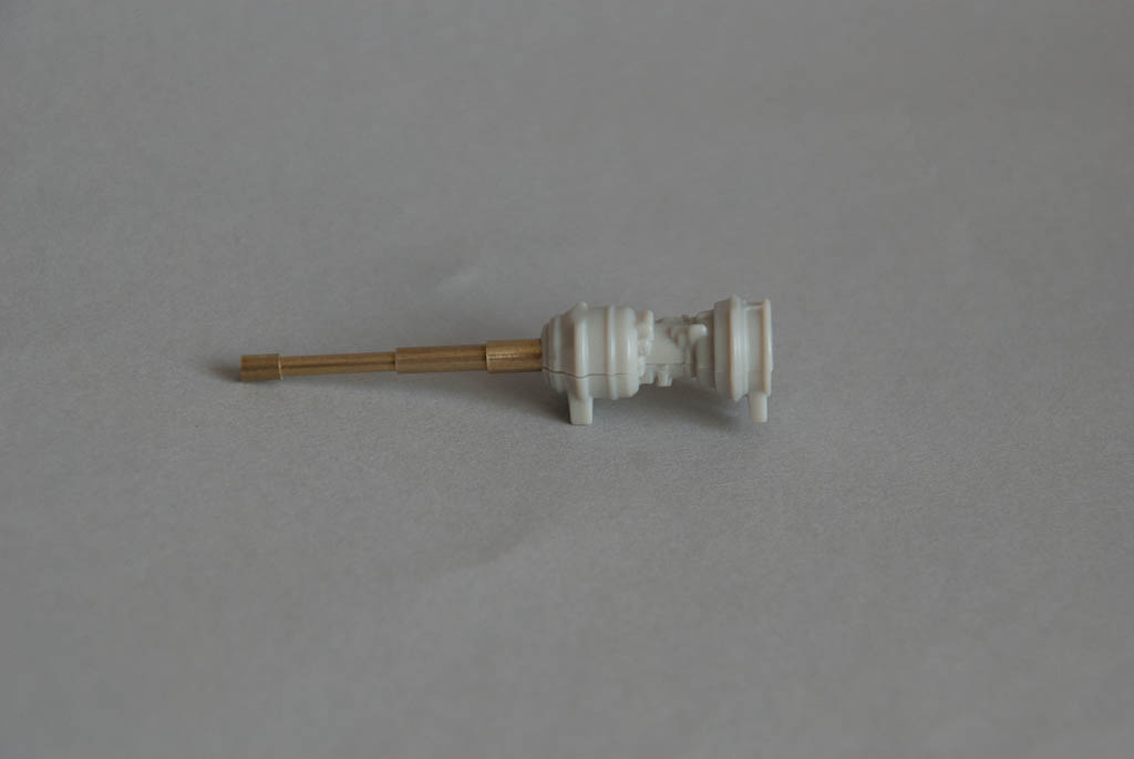
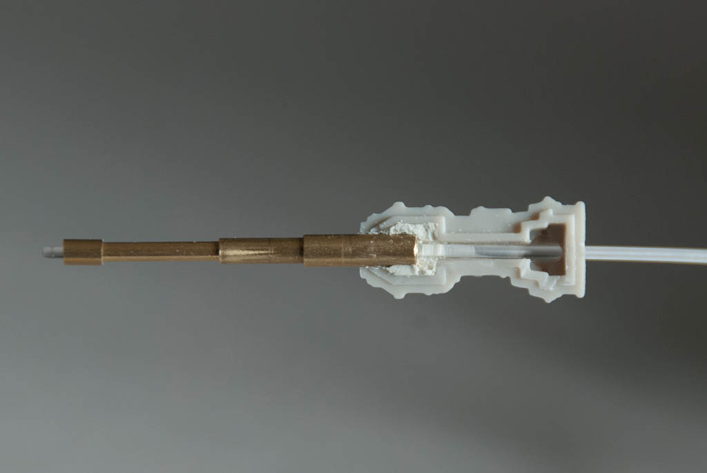
The guns are to be lit using 1.5mm fibre optic, connected to the gun LED inside the fuselage. The guns are moulded in 2 halves, but one half has the complete solid gun barrel which makes it much more difficult to hollow out than if it was also in 2 parts. It could be possible to carefully drill out the centre of the barrel but I decided it would be much easier to make new ones from brass tubing. The barrel has 3 different diameters along it’s length – I found that brass tube in 3/32″, 1/8″ & 5/32″ is almost an exact match for the kit barrel and each section of tube slips over the next smaller diameter perfectly. All the bits of tube were cut and assembled into the new barrels with a touch of superglue. I made them 1/4 longer than the protruding bit of the kit parts so that they could be embedded inside the gun body.

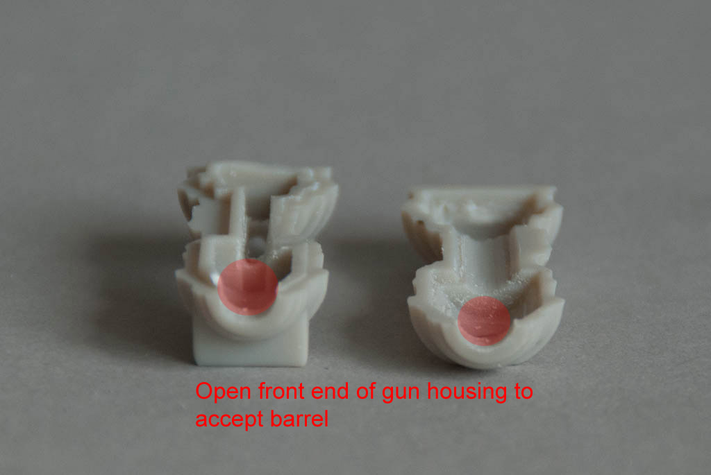
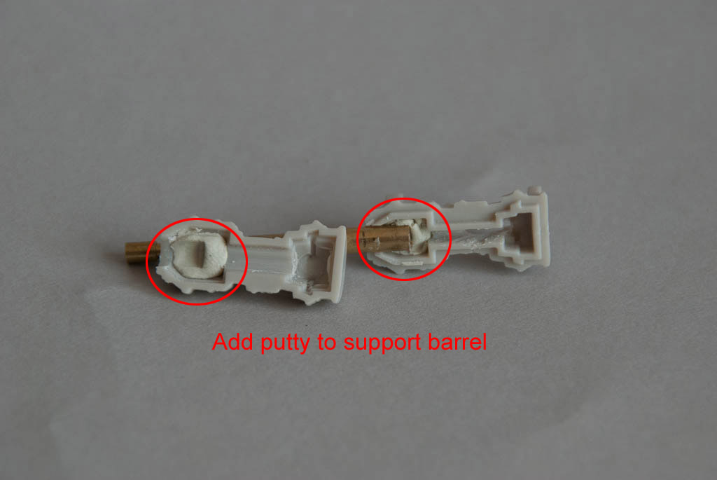
The plastic barrels were sawn off and a 5/32″ hole was opened up in the end of the guns – I just used a round file on each half until the hole was the right size. I added a small ball of putty inside the front of each body half, inserted the brass barrels to the required length and then squeezed the whole assembly together, making sure the barrel protruded straight out and was not drooping, then gently separated the body again and put aside for the putty to set.
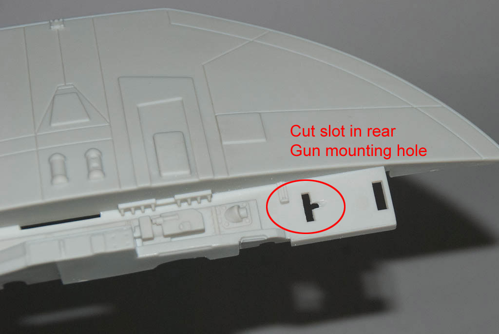
The 1.5mm fibre optic is the perfect size to fit inside the gun barrel but because it is quite thick, it is not very flexible. This creates a few issues trying to get the fibre into the gun. It needs to come from the main body, into the wing tip section, and then up through the gun mounting peg and into the barrel. Due to the inflexibility, it’s necessary to cut angled slots in the gun body and mounting location of the wing tip so that the fibre will pass through more easily without tight bends. I started cutting a slot in the bottom gun body piece and then widened and angled it using a thin round file – the goal was to get as shallow a path as possible up into the body.

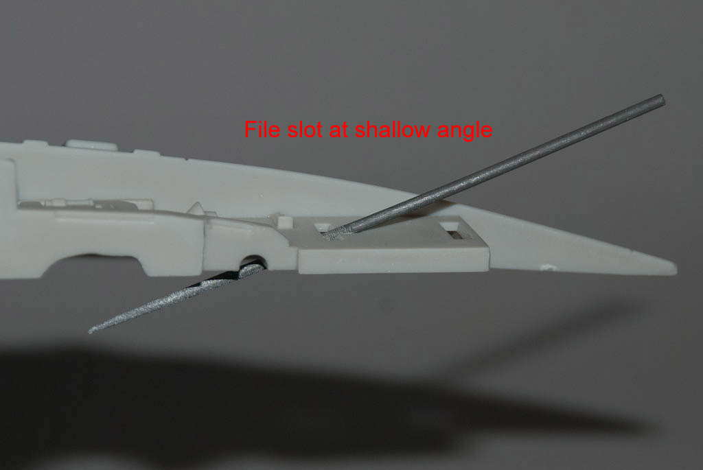
Similarly where the rear mounting foot fits into the hole in the wing tip upper section, I created another angled slot to match up. When the 2 pieces are together, the fibre can then pass up from inside the wing tip to the gun body with as little bending as possible, yet still be almost totally invisible from the outside.
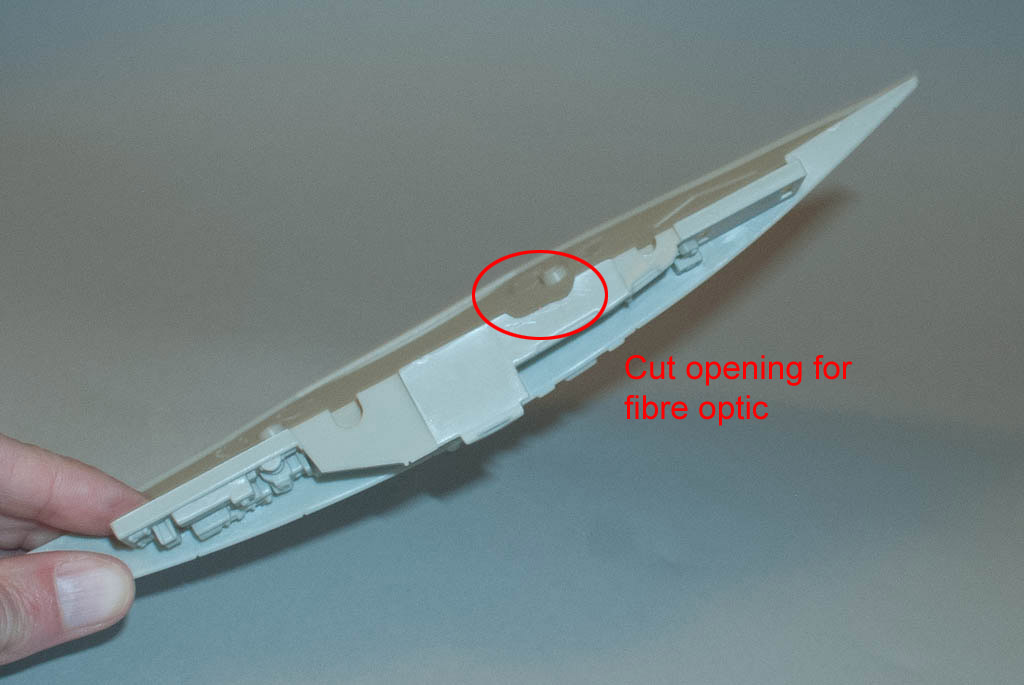
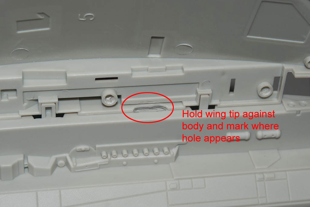
To get the fibre from the main body into the wing tip, a hole is needed in each. A suitable place was selected in the side of the wing tip and a slot opened up with a file. Holding the wing tip up to where it attaches on the main body, it’s easy to mark where the corresponding hole needs to be.
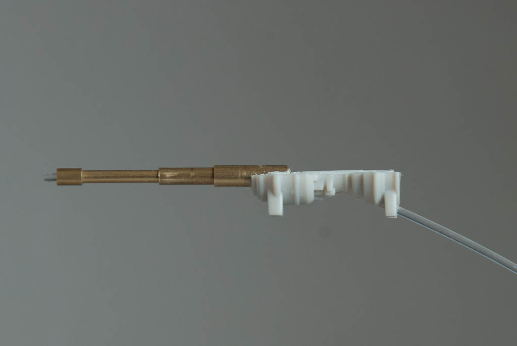
Finally a check that everything lines up – the fibre goes through the wing tip side, up into the gun body, and out of the barrel.
