Lighting Module for Max Factory Gypsy Danger

Yet another lighting project on the go – this time for the new Pacific Rim Gypsy Danger kit from Max Factory / Plamax.

The kit does come with a small lighting module, but this is rather disappointing. It uses a single LED to illuminate both the chest turbine, and, through a rather convoluted arrangement of clear pieces, the visor too. One big advantage is that the kit has been designed to allow access to this module for battery replacement once assembled.

I wanted to have a turbine effect more like as seen in the film, so have designed a system that uses a ring of LEDs (and one in the middle) that can be animated in a rotating configuration. Space is very tight, so I have split the design up into 3 pieces – An LED board that sits behind the clear turbine cover, a main driver board that fits into the main chest cavity and which provides the animation for the LEDs and also contains an additional LED to shine directly up into the head to illuminate the visor better, and finally a power board containing the battery and on-of switch. The power board sits under the main board but can be easily unplugged and removed from the model to facilitate changing of the battery.

Zvezda/Revell Star Destroyer Lighting Module

Whilst waiting for the Zvezda Star Destroyer to become available through Revell in Europe, I have started putting together a speculative lighting controller board.

This features a flickering effect for the 3 main engines and the 4 auxiliary engines. It also provides 12 additional static (non flickering) LEDs to provide light for the windows via fibre optic strands.

The board has been designed primarily for battery power and has a total current draw of around 60mA – which should give may hours of operation on a set of 3 AAs. Alternatively there is also an on-board voltage regulator that can be fed from a 7-12v wall adaptor.

This test build features cool white LEDs for the engines and warm white for the windows

Bandai Star Destroyer Part 3

<< Part 2

Everything is just about there. The fibre marries up with the central LED much better now. I’ve added some short lengths of 1.5mm fibre at the rear of the 3 main engines to act as light pipes – this gives a much better effect inside the engine bell than just having a hole.

The last thing to resolve is the wires for the battery supply. I want these to run down through the stand, but it’s just a bit too small to get 2 bits of my smallest stranded cable down. For now I’ve used 2 bits of solid core wire wrap wire – these are plenty small enough, but will not survive much manhandling or moving of the ball & socket joint. Need to come up with a better solution…

For now here’s some beauty shots. The ship was primed in a just off-white colour and then given a wash of Concrete Flory Wash. Once dry, the excess was wiped away with a slightly damp sponge & that’s it. I’ve used a focusable LED torch several meters away as a slight source in an attempt to simulate the parallel light of a far-distant sun…

Bandai Star Destroyer Part 2

<< Part 1

Small amount of progress before Christmas got in the way. After trying to use 0.5mm fibre for the smaller engines I gave up due to the problems with bending them up to the LED – they were just too stiff over such a small length. So I downsized to 0.35mm which works better but still had some issues with the off-centre LED placement, so I have decided to take the hit and do a PCB revision with a few tweaks:

  •  Small engine LED moved to centre and brought back a few mm to help with clearance around the fuselage top.
  •  Larger slots at back of PCB to aid routing lower fibres up to top of PCB.
  •  Increase clearance around side holes for a better fit.
  •  Rework main engine LED pads to allow a different type of SMD package, and remove unused through-hole pads.

Just waiting for the new boards to arrive, but here’s the old one in action with the fibre.

dsc_9219 dsc_9218

Time passes..

The new boards have arrived, so quickly made one up for comparison. Having the engine LED in the centre is much better, and I was able to go back to the 0.5mm fibre for the small engines. Everything also fits better inside, and the top of the Destroyer fits on with ease.

dsc_9225 dsc_9227

dsc_9229 dsc_9230

Part 3 >>

Bandai Star Destroyer Lighting Module

I recently acquired Bandai’s new “palm size” Star Destroyer kit – A great little kit!. There’s a tiny bit of space inside so I thought I’d have a go at doing a module for lighting the engines.

There are 3 LEDs that line up directly with the main engines, and a fourth to be used as a source for 4 bits of fibre optic to light the intermediary engines. All of these LEDs are programmed to produce a flicker effect. A final static (no flicker) LED can be used to feed fibre to light windows in the Destroyer, although I’m not sure I’m going to bother with that. Too fiddly!

All the engines need carefully drilling out. I used 1.5mm for the main engines and will be fitting 0.5mm fibre to the intermediaries.

Power wires come off the bottom of the board and are designed to feed out through the stand mount – again these need to be drilled out to accommodate.

So far so good.

dsc_9212

Main engines, rear view

dsc_9215

Part 2 >>

Pegasus Nautilus Part 3

<< Part 2

The original plan was to use 3mm LEDs in the spotlight and wheelhouse, but after playing around for a while I concluded they were going to be too big. The solution was to use a couple more surface mount LEDs but soldered onto wires to make super small freestanding lights. Using 1206 sized packages it’s still possible to manually solder single core wire-wrap wire onto the contacts with a fine point soldering iron bit. Holding the LED in some reverse action tweezers (the sort that grip til you squeeze them) really helps for this bit.
Once the wires were soldered, a small blob of clear 5-min epoxy was used to bind everything together securely.

DSC_8684 DSC_8685
I decided to scratch-build a new searchlight from a 2mm length of 3mm I/D styrene tube. The LED sits at the back of this perfectly after a small notch was filed in the back end for the wires. The grille on the front of the searchlight was replicated by gluing 3 very thin styrene rods across the front end of the tube. Once the glue had hardened, the excess rod was trimmed off and the edges sanded flush with the tube.
DSC_8679 DSC_8682 DSC_8720
After priming, the inside was painted silver to help reflect the light. The LED was glued in place with more 5-min epoxy and once set, a small cone of Miliput was added to the back to match the original kit part.
DSC_8727 DSC_8728 DSC_8729
The hole where the searchlight mounts on the wheelhouse roof was drilled through so the wires can pass inside when the light is attached.
A second wired LED was glued onto the ceiling of the wheelhouse just a bit further back than where the searchlight wires will come in. The wiring for both was then routed forwards along the ceiling and into 2 groves cut into the ceiling where the wall of the photoetch wheelhouse assembly will fit.
DSC_8732 DSC_8733

Pegasus Nautilus Part 2

<< Part 1

One of the problems I’ve found with photo etch is that paint doesn’t stick to it very well due to the very shiny finish. Ideally you should use an etching primer that bites into the surface before curing but I didn’t have any of that around so I had a go at replicating the process instead.

I had some Ferric Chloride left over from etching some prototype PCBs many years ago, so I used a few drops to make a much much weaker solution than would normally be used – all I wanted was to cut into the metal surface microscopically, not dissolve it away.

After a 30 minute soak, then good wash, the parts had a nice tarnished and very matt surface. This allows regular primer to stick very well indeed.

DSC_8597 DSC_8600 DSC_8616

Painting of the lounge proceeded. I went for a fairly basic colour scheme, light gray/green for the walls, oily steel for the floor plates and dark brown for the woodwork, with red leather covering on the sofa & chair. The books were blocked out in a range of colours with just the odd one out of place to jumble things up. I had to keep telling myself most of this will not be visible!

DSC_8601 DSC_8602

A quick test with the lights overhead verified that some of it will be visible – although there is still the main window panels to go in yet which will restrict sight further. I don’t think I will use the PE storm shutters on the windows.

DSC_8611 DSC_8614 DSC_8615

I also shot a short video showing some typical lighting sequences – these have been shortened for the video, I will probably leave a minute or so between changes in the final model.

Part 3 >>

Pegasus Nautilus Lighting Module – Part 1

I’ve started work on an animated lighting module for the Pegasus Nautilus submarine. This kit features a detailed interior, which is improved even further by the ParaGrafix photo-etch detail set. This includes an additional interior for the forward wheelhouse as well as extra details for the main lounge/observation room. The ceiling of the observation room features 16 lighting panels, so I decided the easiest way of tackling this project was to design a module that had 16 LEDs mounted on the bottom that line up with these panels. After opening up the panels, the PCB will sit on top and shine through into the observation room with no messy wires. Part of the PE set includes some nice perforated panel covers which will improve the overall lighting effect.

Apart from the ceiling lights, there are 4 exterior spotlights, two on each side of the hull at either side of the big observation windows – obviously designed to illuminate the murkey depths. Finally an interior light is needed to illuminate the wheelhouse and one more for the searchlight mounted on the top of the vessel.

There’s not much the lights really “do” but rather than just be static I decided to go with a fairly simple system that turns the lights on and off in various sequences.
A quick circuit was drawn up based around an Atmel ATTiny84 micro controller – this has enough outputs to drive the ceiling lights as 4 strips of 4, 2 pairs of spotlights, port and starboard, the wheelhouse, and the searchlight. It’s small enough to fit everything easily on a PCB no bigger than the top of the observation room.

The four spotlights protrude from the ends of triangular wedge shaped strips that attach to the sides of the hull. I started off gluing the halves of each wedge together. A small end cap holds the clear piece representing the spotlight window. Normally this clear part must be attached before the end cap is secured in place due to the way it is partially covered by an alignment lip on each side. I wanted to keep the clear parts of until initial painting was completed, so I removed the lip overlap from the end of the wedge to allow the window to be dropped in later.
DSC_8562 DSC_8563

A 5mm LED fits quite snugly into the back of the window. The LED and wires will need to be fed through from the inside of the hull, so I opened up a hole in the side of the hull roughly behind where each LED will sit.

DSC_8561

In order to see into the wheelhouse though the top windows, it’s necessary to open up the area that normally blanks these off from part C3.

DSC_8564 DSC_8565

Opening up the light panels in the ceiling is quite a tedious job. I started by drilling 2mm holes around the inside of each panel, then cutting out the remaining plastic between the holes with a knife. The inside of the panel was then filed into a clean rectangle. You don’t have to be too precise here since the PE panel cover will hide any untidiness.

DSC_8566

When fitting the PE crossbeam details, pay attention to the fact one side is about 1mm shorter to the other side (due to how the pipes of the organ on the back wall are arranged). Whilst doing a test fit after this stage I discovered a much larger issue – the detail end-pieces on the longer beam also foul the top of the bookcase on the other wall! There is no mention of this in the PE instructions at all. I had to file down the points on the end of the beam, and also file a 2mm wide slot into the top of the bookcase to get the ceiling panel to fit properly into the side wall lugs.

DSC_8567 DSC_8569

Attaching the PE light panel covers is quite fiddly. I found the best way was to put a couple of spots of CA on the raised lip of the panel hole, and then pick the covers up with needle-nose tweezers through a couple of the holes in the PE and then lower into place and hold until the glue grabbed. With the tweezers in the holes it’s relatively easy to ensure each panel is correctly positioned and square.

DSC_8574

A PCB was draughted up and sent off for manufacture. I chose to go with a white solder resist coating rather than the traditional green as this will help spread the light inside each of the lighting panels. After about 2 weeks, a parcel of boards arrived and I set to work assembling one. With the exception of the LEDs for the spotlights, searchlight and wheelhouse, all the components are surface-mount types. The 16 observation room lights and their series resistors are on the bottom and everything else is on the top. Connectors were added for all the other LEDs – not really necessary but it does mean the board can be completely removed during assembly if necessary.

DSC_8580 DSC_8581

Once assembled, a small bit of code was put together to fade the lights up and down in a semi-random sequence and uploaded to the microcontroller. This will probably be tweaked a bit as the project progresses.

DSC_8584 DSC_8590 DSC_8596

Part 2 >>

TARS Part 2

<< Part 1

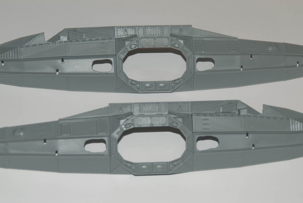
Fabrication has started in earnest. I decided to go with the most complicated piece first – possibly not the best approach but I reasoned if I failed to do this, the whole project would be off.

TARS Top

The first task was to produce some stock from which to machine all the pieces. I made a column from sheet styrene 160mm x 30mm x 20mm – big enough to make half of one quarter of the main body – this is about as big a piece as I can work on in one go on the mill. It was long enough to also include some spare material at the end that I could use for mounting the piece securely on the workbed.

A silicone mold of the column was poured and left to cure. In this I then cast a slab of urethane resin as my workpiece.

The first job was to mount the resin on the mill and then machine one surface completely flat (known as facing). This then becomes the bottom face and all subsequent operations are then guaranteed to be perpendicular or parallel to this face. The block was 20mm thick and the final thickness needed to be 16.7mm so I took off around 2mm at this time using a 3mm end mill. This was the first of several long, noisy and dusty operations! The process took around 30 minutes, milling off the resin manually layer by layer. Holding the vacuum cleaner hose as close to the cutter as possible as it worked sucked up the vast majority of the dust and swarf, but a fair amount still escaped, covering everything in a snowy layer!

Job 2 was turn the block over and reduce the thickness to 16.7mm. This and all subsequent operations were done via CNC. The data from the Sketchup drawings was exported to a series of DXF files which were then imported into CAM software. This allows you to generate the g-code instructions for the CNC controller that tell the mill where to go and what to do.

After watching it grind away for another 20 minutes, my piece was now exactly the right size on one dimension!

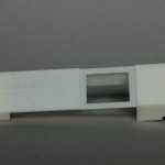
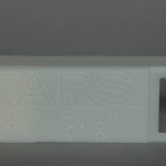
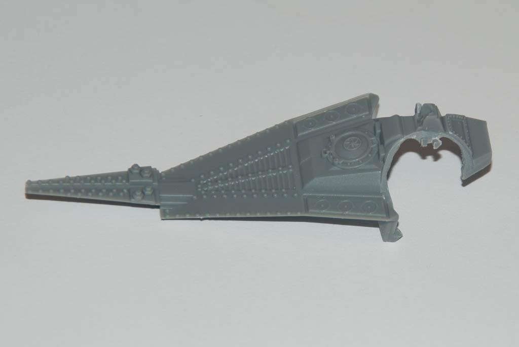
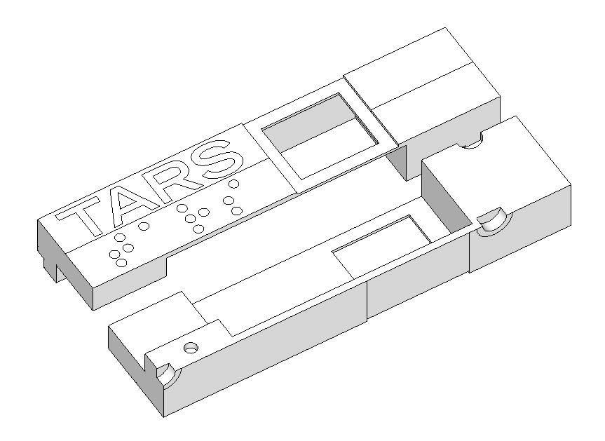
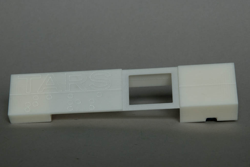
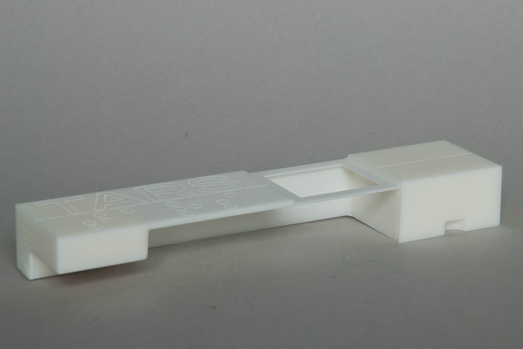
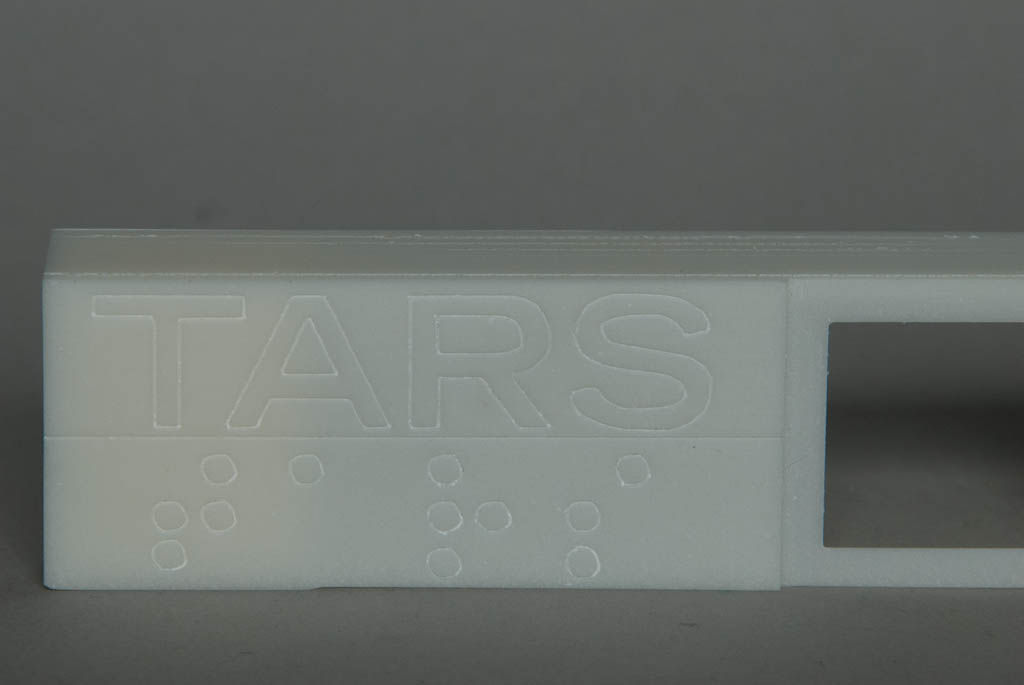
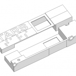
Job 3 was to engrave all the detail onto the front surface – the TARS lettering, the braille underneath and the panel lines. This was quickly achieved using a 45 degree “V” engraving cutter. I figured that it was best to do this first since everything else was going to take some time and I’d hate to mess things up on the final hurdle!

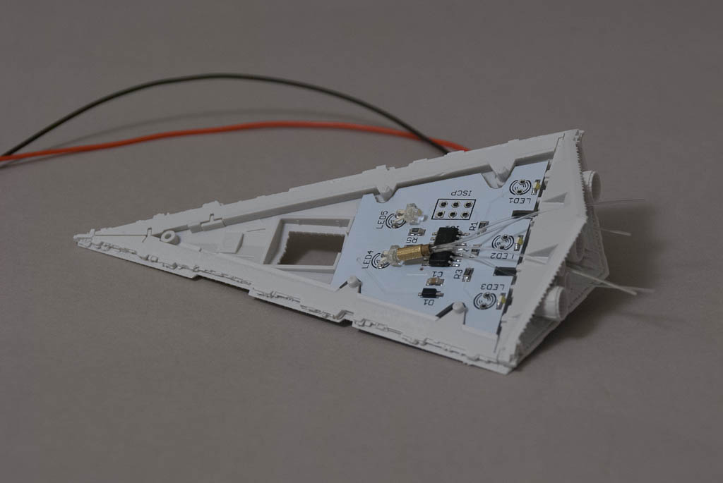
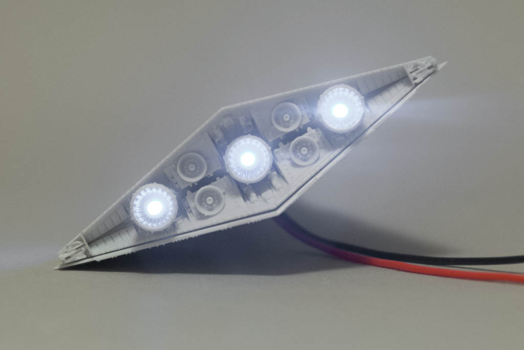
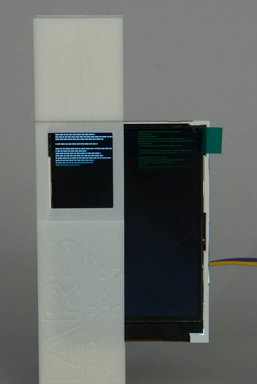
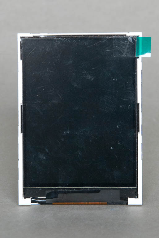
Job 4 was to create the recessed strip in front of the two screen holes which will hold some tinted material, and the two screen holes themselves.

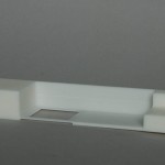
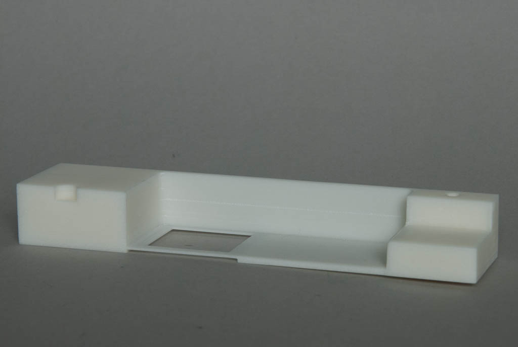
I flipped the piece over and started on job 5 – removing the bulk of the resin inside the piece to allow for the display board. This was another long operation and nearly ended in disaster. By some miscalculation on my part, it ended up going deeper than it should – the recessed strip at the front should have ended up 1mm thick, but actually ended up being 0.5mm! Luckily it’s just about salvageable.

The last big operation was to remove the channel at the bottom of the piece. this is only really to allow the wires up from the battery back and in hindsight could have been a lot smaller ( = quicker to mill!)

2 small recessed were cut which will contain the magnets used to hold the whole assembly together. A half circular one at the top which will mate with the same in the other half, and a full circular one at the bottom side.

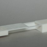
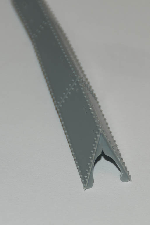
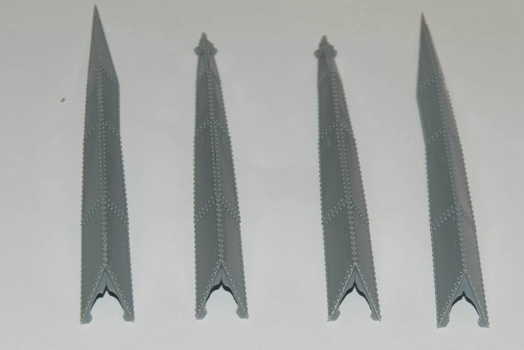
All that remained was to mill the outside dimension of the piece to free it from the excess stock. Well not free entirely – two small holding tabs were left, one at each end to ensure everything remained steady as the rest of the machining progressed – much like plastic sprue attachment points.. Once finished, these were cut through with a micro saw and the remaining nubs sanded flush.

Overall it came out better than I hoped but not entirely perfect. There’s a small bit of scoring on the sides due to the mounting not being secure enough which caused the piece to move during machining and also I think I was cutting a bit too fast, overloading the drive mechanics a bit. Nothing that won’t polish out. But it was a good learning exercise!

There is still more work to be done on this piece on the outside-side – more panel lines and holes for magnets but these have yet to be CAD-ed up.

DSC_7294 DSC_7295 DSC_7296 DSC_7297 DSC_7298

TARS from Interstellar

After the success of adding a working display screen to Gerty last year I’d been thinking about doing the same to something else. Re-watching Interstellar a while ago made me realise TARS the robot would be a great choice for a scratchbuild project. TARS himself is a relatively simple design, and there were some blueprints on the Blu-ray extras that showed the overall measurements of the full sized prop. From this it was easy to extrapolate all the others.

The first task was to draw up the parts in Sketchup full size and then resize down to get some figures to work with. A 1/6th scale model seemed to be a good place to start.

Tars-Assembled-1 Tars-Assembled-2

TARS has 2 portrait orientated screens behind a tinted facia. Initially I figured I could use a single small LCD in landscape mode and use a portion of the LCD for each screen. The modules have a small plastic surround that holds the glass LCD in place. It’s only a couple of mm on 3 sides but unfortunately one end is much thicker to accommodate the flexible connector to the controller electronics. This means a) with the module in landscape orientation, the active LCD area is offset from one side and b) the wide border is too wide compared to the border of the TARS screen on one side. So I have to use the display in portrait mode, which in turn means most of it will not be used.

Looking around at available LCDs, a module with a 2.8″ active area seemed to be in the right ballpark – this would just be wide enough in portrait orientation for both TARS’ screen at exactly 1/7th scale. Slightly smaller than originally planned but this will alleviate some other issues to do with making the body too.

I intend to mill out and engrave the body from solid blocks of probably just resin (or maybe PU foam) but my small CNC mill has a very limited work area. The next job was breaking TARS down into manageable pieces. The arms were easy; these can be split in 2 in the middle. Despite the inside face of the arms being slightly different (no fine detailing and pivot point locations) I can make 2 complete arms from 4 copies of one half. The body is slightly more complex – it’s basically 4 pieces, 1 for the top front (including name and holes for screens) and 3 identical ‘blanks’ for the others.

The front of the LCD needs to be as close to the inside of the bezel around the screen holes as possible, which means the top part will need to be almost hollow. A battery pack of 3 AA cells will power the module, and this will be inside the bottom half, so each of these will need to be hollowed out as well, but not to such an extent. Access to the battery pack will be necessary occasionally so my plan is to hold everything together with magnets. These will also be used to hold the arms to the body, allowing both rotational movement and changing of pivot point from top, middle or bottom to provide a number of posing opportunities.

A few more hours with Sketchup and I ended up with this:

Tars-Components
Next up was the electronics. I drew up a design based around an Atmel ATMEGA328 microcontroller (as used in the Arduino development board). This communicates with the LCD over a simple serial interface. I decided to add in some extra components since this may end up being used in other projects – a micro-SD card reader (handy for showing images on the LCD like in the Gerty project) and an expansion connector to allow some of the other spare I/O ports of the microcontroller to be connected up. The board sits neatly on the back of the LCD module and is only a few mm thick.

DSC_7095 DSC_7096
Most of the time, all you see on TARS’ screens is a continual stream of text printing out – the left one is usually white and the right one is green. The LCD resolution (128 x 160 pixels) is far too low to show real text, so this was simulated with single pixels. A loop constructs a line of random length made from words of random length and draws each line out, one letter pixel at a time. This happens simultaneously on both screens. Once a screen is full, it is cleared and the process starts from the top again.

Part 2 >>