TARS from Interstellar

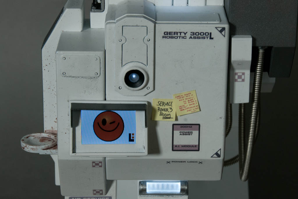
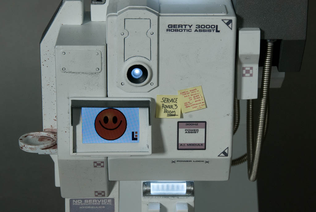
After the success of adding a working display screen to Gerty last year I’d been thinking about doing the same to something else. Re-watching Interstellar a while ago made me realise TARS the robot would be a great choice for a scratchbuild project. TARS himself is a relatively simple design, and there were some blueprints on the Blu-ray extras that showed the overall measurements of the full sized prop. From this it was easy to extrapolate all the others.

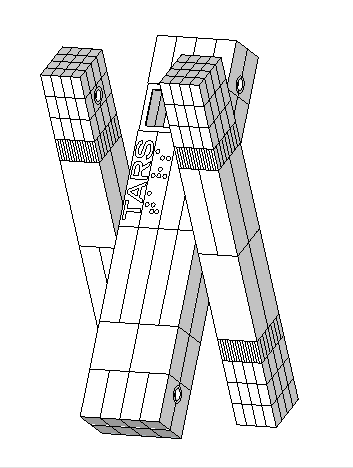
The first task was to draw up the parts in Sketchup full size and then resize down to get some figures to work with. A 1/6th scale model seemed to be a good place to start.

Tars-Assembled-1 Tars-Assembled-2

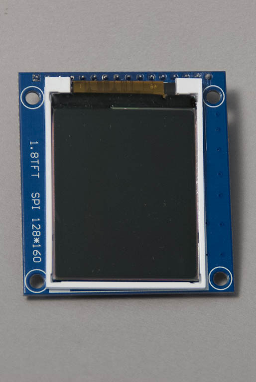
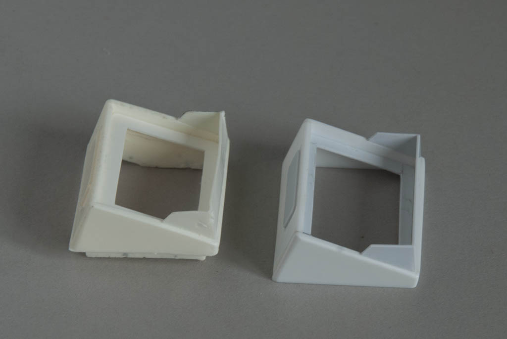
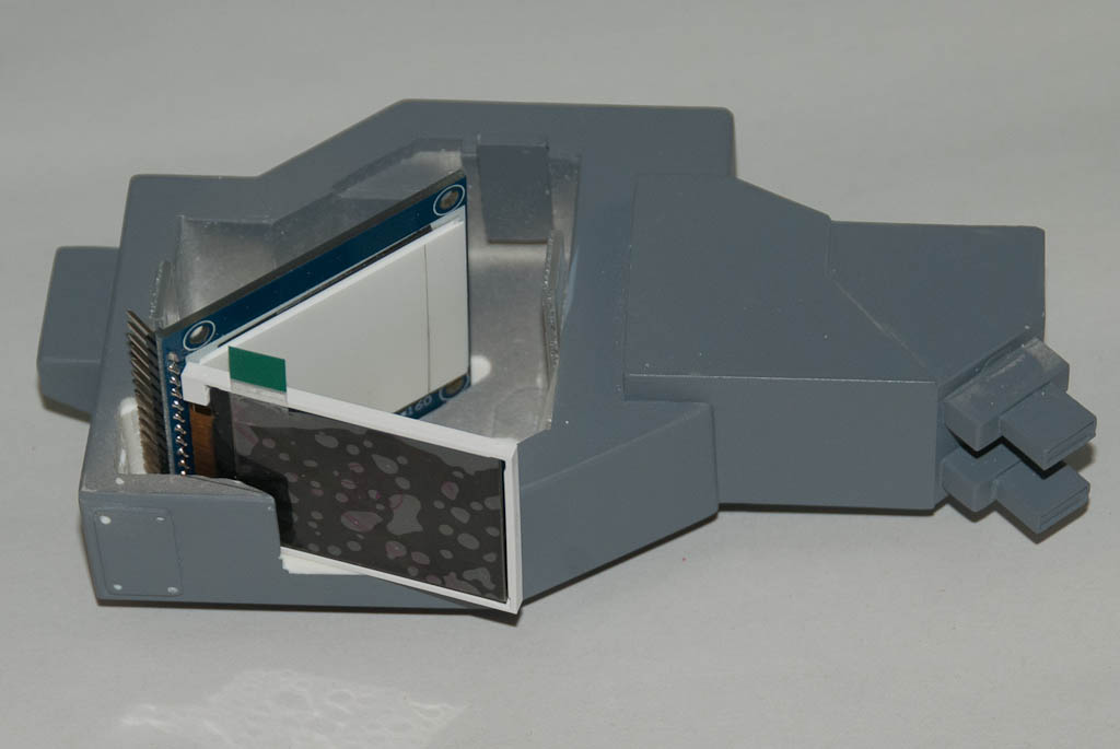
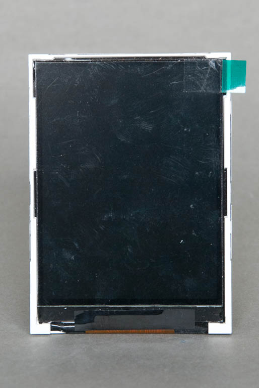
TARS has 2 portrait orientated screens behind a tinted facia. Initially I figured I could use a single small LCD in landscape mode and use a portion of the LCD for each screen. The modules have a small plastic surround that holds the glass LCD in place. It’s only a couple of mm on 3 sides but unfortunately one end is much thicker to accommodate the flexible connector to the controller electronics. This means a) with the module in landscape orientation, the active LCD area is offset from one side and b) the wide border is too wide compared to the border of the TARS screen on one side. So I have to use the display in portrait mode, which in turn means most of it will not be used.

Looking around at available LCDs, a module with a 2.8″ active area seemed to be in the right ballpark – this would just be wide enough in portrait orientation for both TARS’ screen at exactly 1/7th scale. Slightly smaller than originally planned but this will alleviate some other issues to do with making the body too.

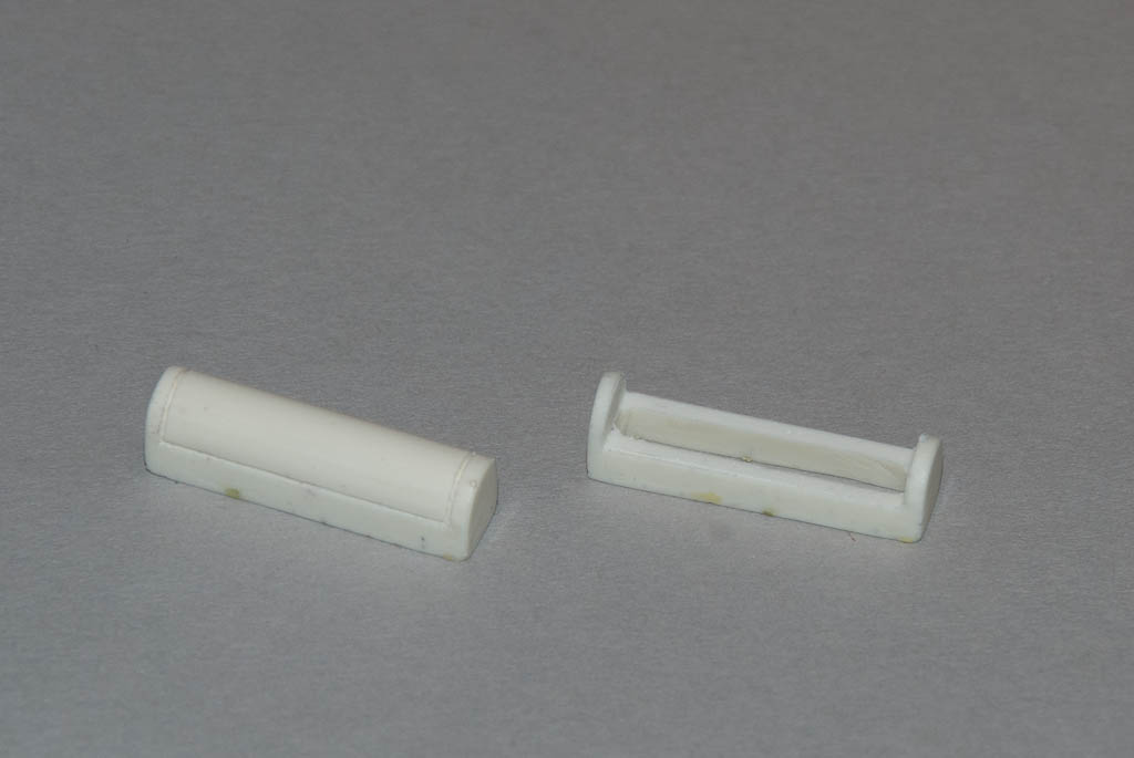
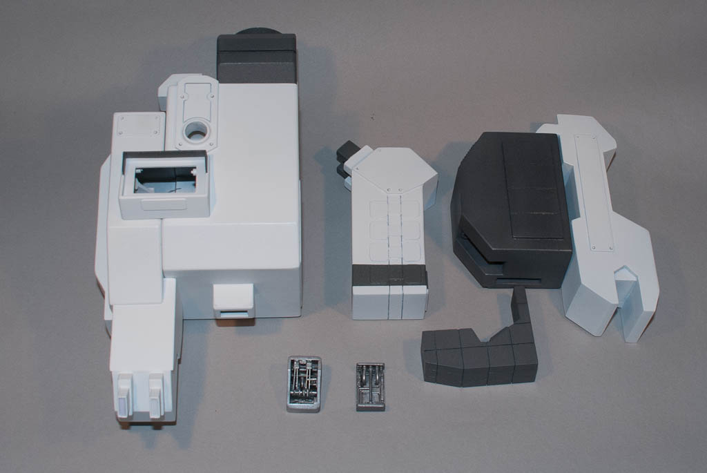
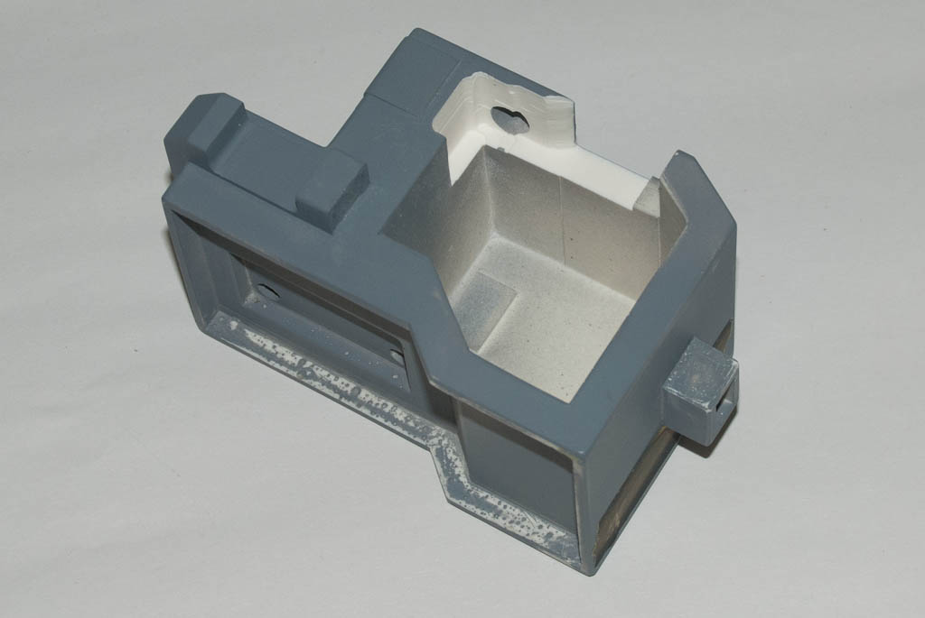
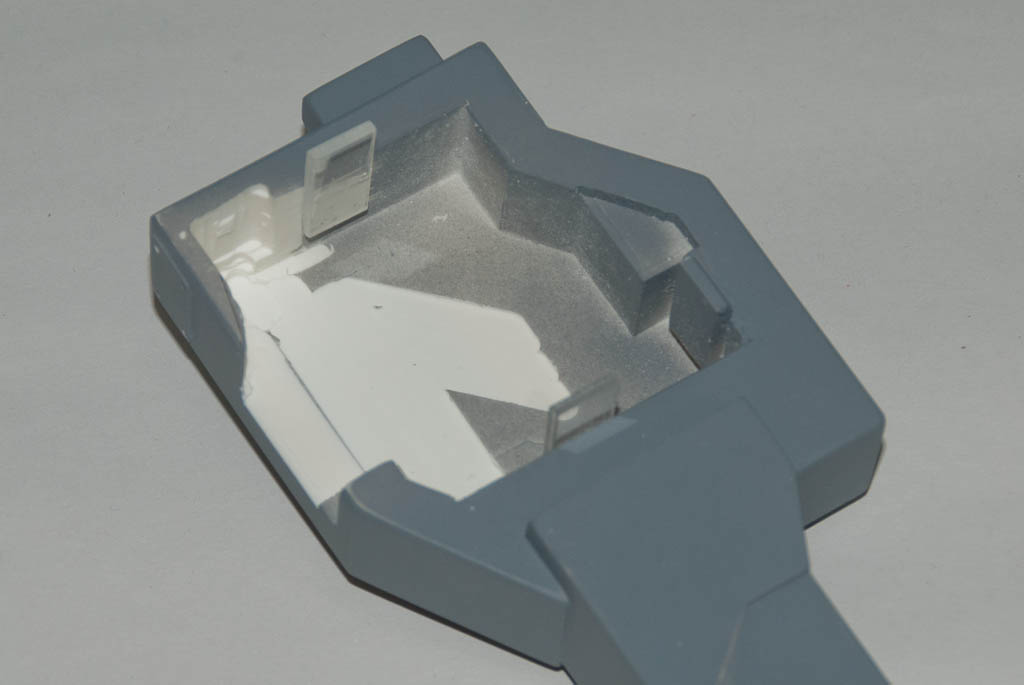
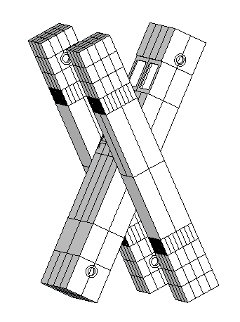
I intend to mill out and engrave the body from solid blocks of probably just resin (or maybe PU foam) but my small CNC mill has a very limited work area. The next job was breaking TARS down into manageable pieces. The arms were easy; these can be split in 2 in the middle. Despite the inside face of the arms being slightly different (no fine detailing and pivot point locations) I can make 2 complete arms from 4 copies of one half. The body is slightly more complex – it’s basically 4 pieces, 1 for the top front (including name and holes for screens) and 3 identical ‘blanks’ for the others.

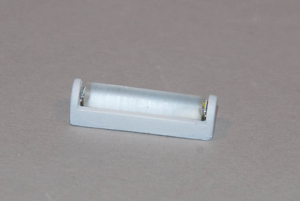
The front of the LCD needs to be as close to the inside of the bezel around the screen holes as possible, which means the top part will need to be almost hollow. A battery pack of 3 AA cells will power the module, and this will be inside the bottom half, so each of these will need to be hollowed out as well, but not to such an extent. Access to the battery pack will be necessary occasionally so my plan is to hold everything together with magnets. These will also be used to hold the arms to the body, allowing both rotational movement and changing of pivot point from top, middle or bottom to provide a number of posing opportunities.

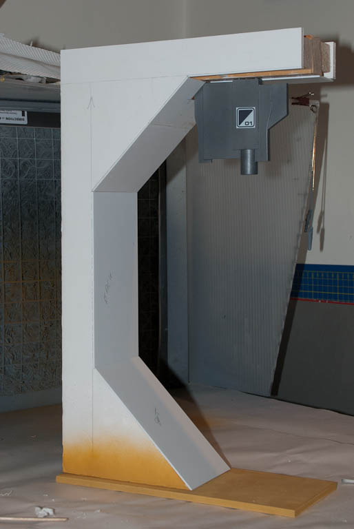
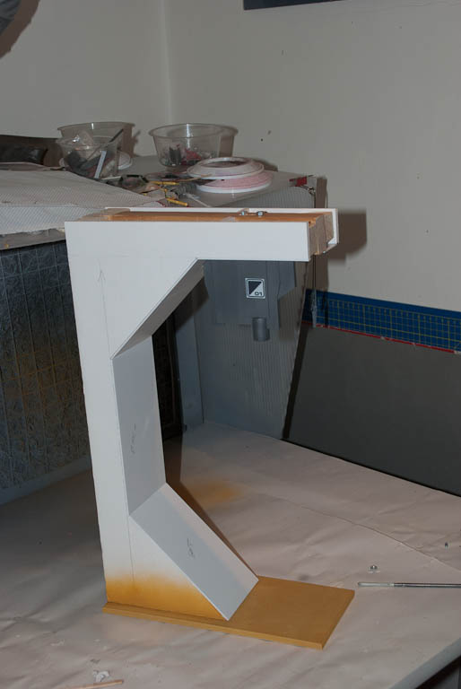
A few more hours with Sketchup and I ended up with this:

Tars-Components
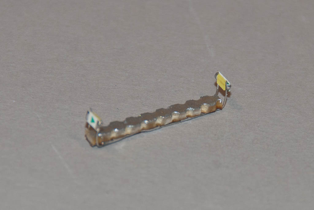
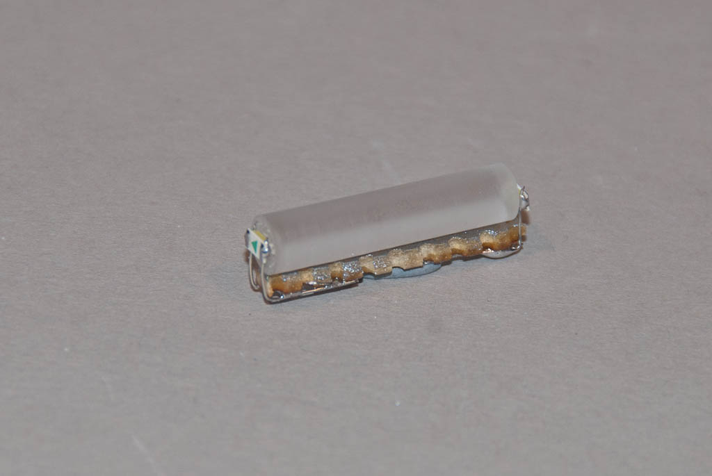
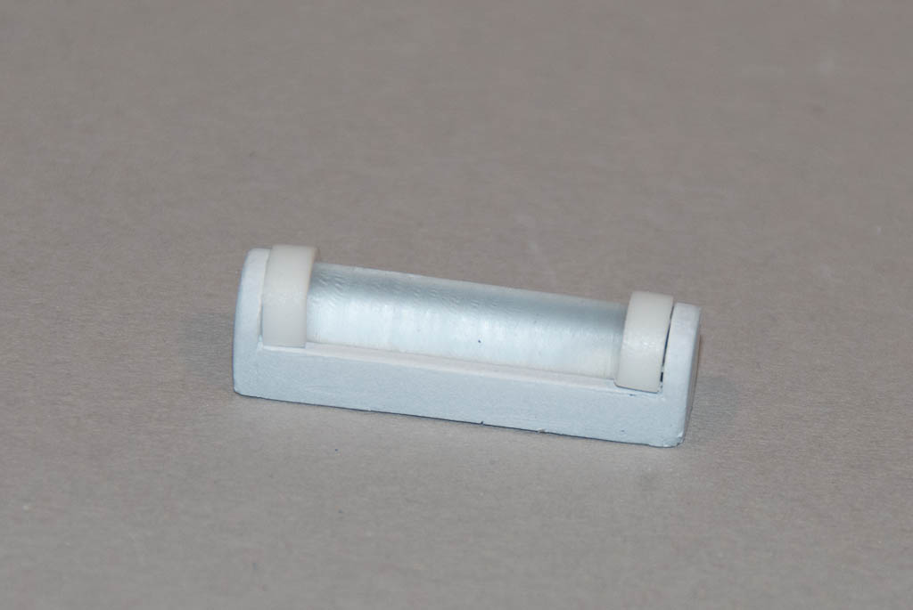
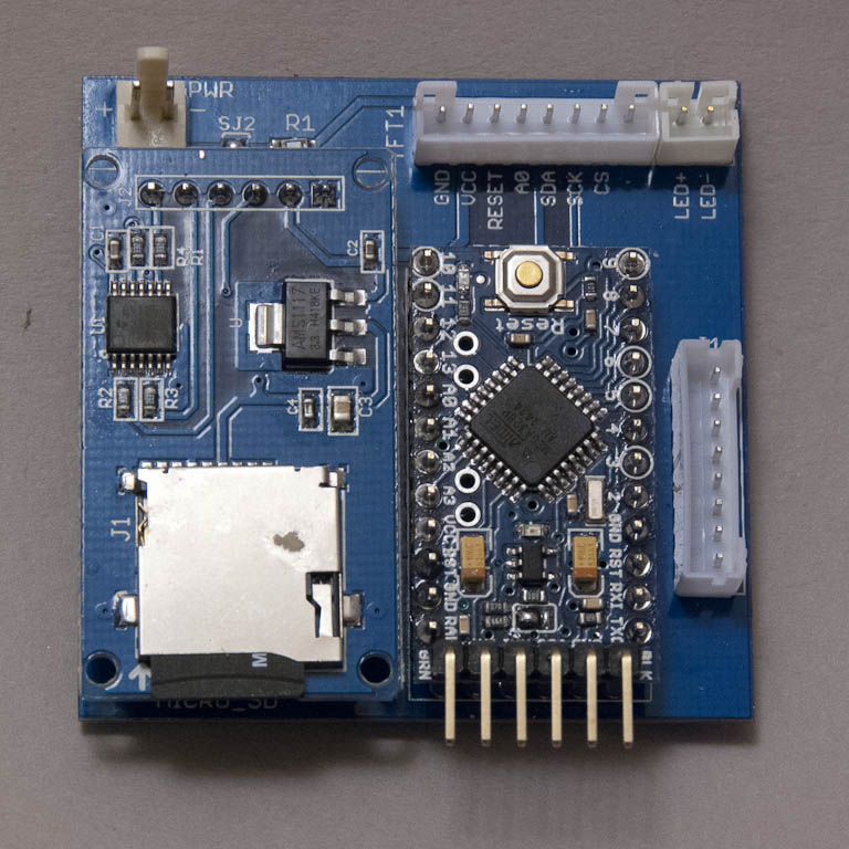
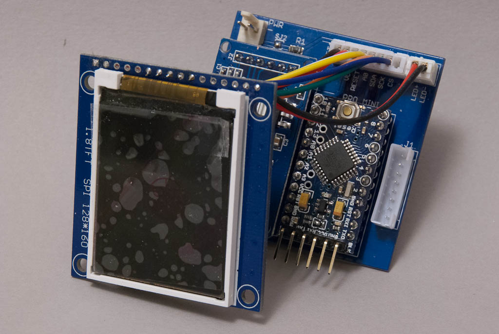
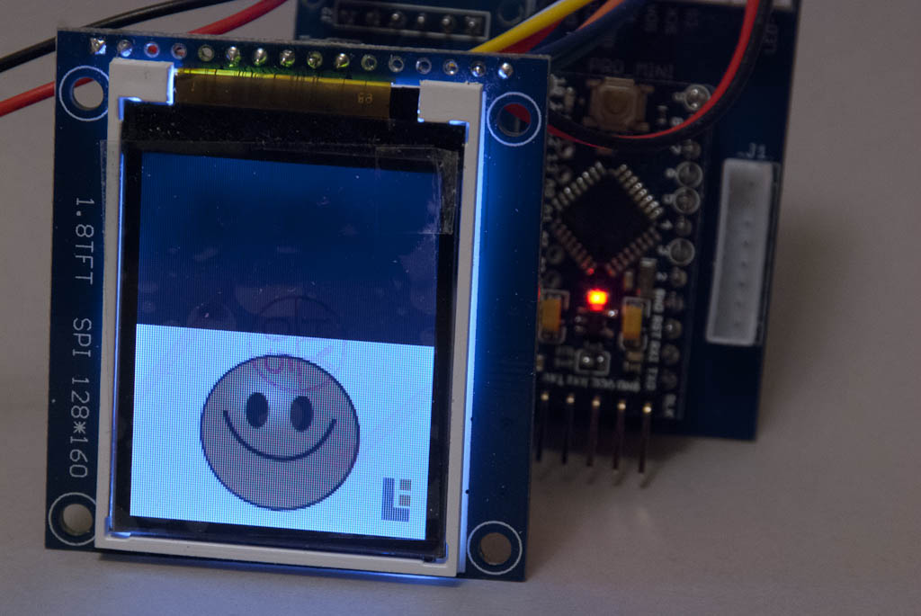
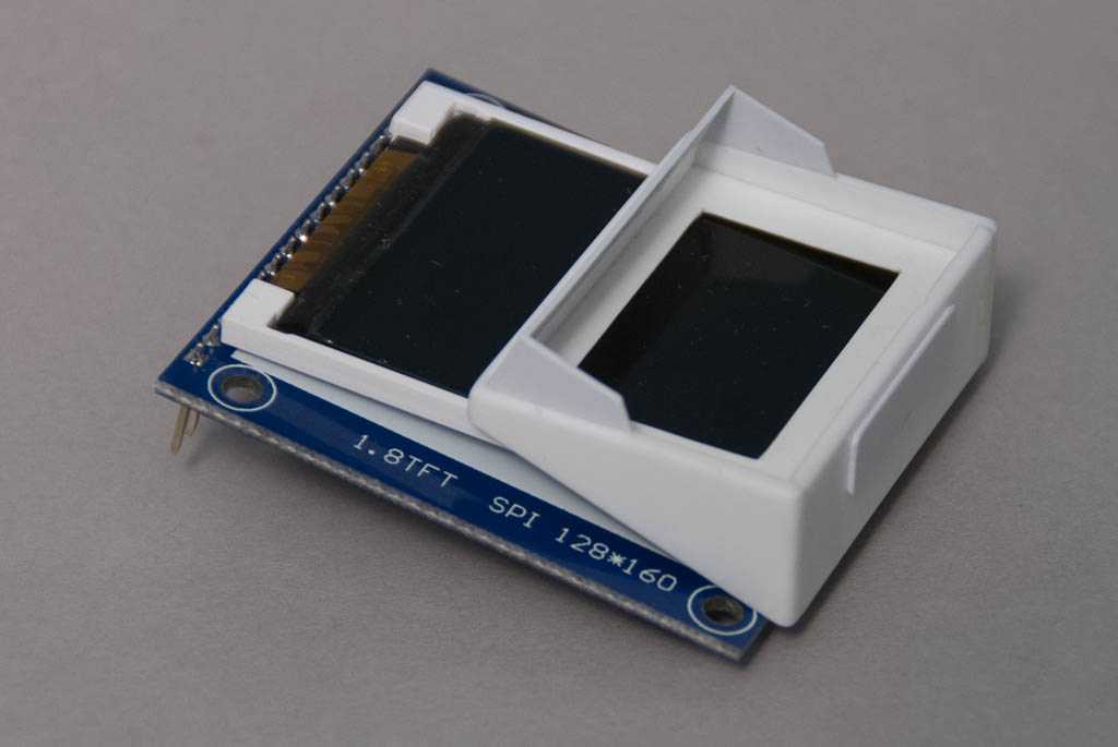
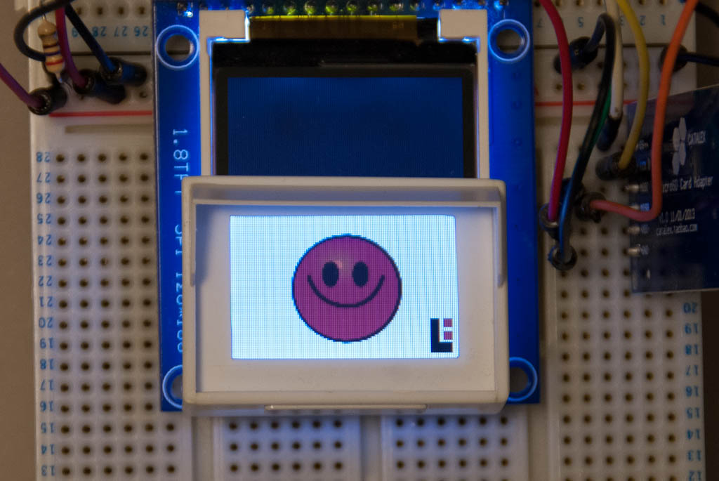
Next up was the electronics. I drew up a design based around an Atmel ATMEGA328 microcontroller (as used in the Arduino development board). This communicates with the LCD over a simple serial interface. I decided to add in some extra components since this may end up being used in other projects – a micro-SD card reader (handy for showing images on the LCD like in the Gerty project) and an expansion connector to allow some of the other spare I/O ports of the microcontroller to be connected up. The board sits neatly on the back of the LCD module and is only a few mm thick.

DSC_7095 DSC_7096
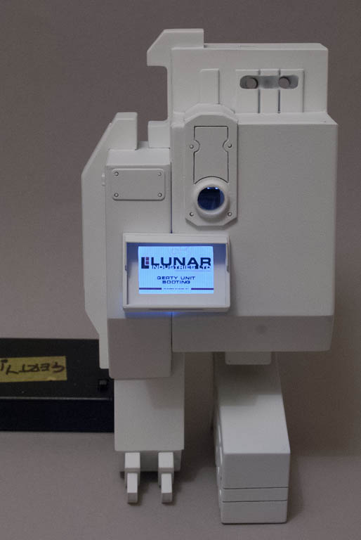
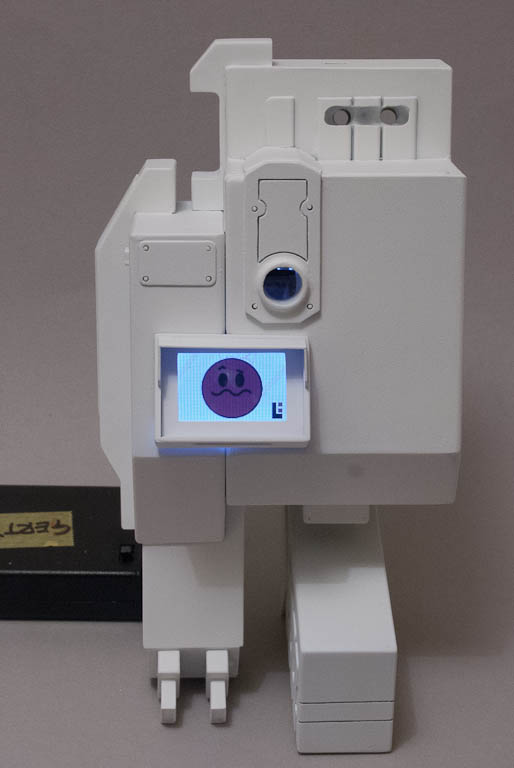
Most of the time, all you see on TARS’ screens is a continual stream of text printing out – the left one is usually white and the right one is green. The LCD resolution (128 x 160 pixels) is far too low to show real text, so this was simulated with single pixels. A loop constructs a line of random length made from words of random length and draws each line out, one letter pixel at a time. This happens simultaneously on both screens. Once a screen is full, it is cleared and the process starts from the top again.

Part 2 >>

Gerty Part 5 – Finishing Off

<< Part 4

There are 2 fluorescent strip lights which are cast in resin and intended to be lit from behind by a row of 8 LEDs provided in the kit. I decided to try and create a more energy efficient light to prolong battery life. After a fair bit of experimentation and prototyping, I came up with the following solution:
What would be the clear section of the resin part was carefully removed using the milling machine.

DSC_5434
A sliver of stripboard that was trimmed down to fit inside the resin part, whilst still having the remains of 2 copper strips running along its length. One of the copper strips was then cut in the middle of the board to electrically isolate one half of each end.
a thin piece of solid core wire was soldered onto each copper strip so that it protruded past the end of the stripboard.
Now for the really tricky part – a surface mount cool white LED (1206 size) was soldered onto the protruding wires at each end, about 5mm from the end of the board. The LEDs were arranged so that both cathodes were connected to the wires on the strip that runs the length of the board, and the anodes were connected to the wires on the 2 separated strips.
The LEDs were then carefully bent up so they faced inward to each other from the top side of the board.

DSC_5468
A couple of pieces of clear acrylic rod were turned down on the lathe to about 5mm in diameter, and were gently sanded with 800 grit wet & dry. This will help diffuse the light that comes later.
Each piece of acrylic rod was trimmed in length so that they fitted exactly between the 2 LEDS once the stripboard was mounted inside the resin light unit. The ends of the rod were countersunk a little to help the LED sit as flush as possible with the end.

DSC_5469 DSC_5470
Finally some 2mm wide end covers were cut from some 8mm styrene tube – first a 2mm ring was cut from the tube, then a near 180 degree segment was cut so that it sat neatly over the acrylic rod, whilst coveing up the LED and connecting wires. This took several attempts to get an exact fit.

DSC_5471
3 wires are soldered to the bottom of the stripboard, one common connected to both cathodes, and one for each anode. These will be connected to the controller unit in due course.
Meanwhile all the major components were sprayed white, or dark gunmetal as appropriate. They were then given several coats of Johnson’s Wax (aka Future Floor Polish) to provide a glossy surface on which the many decals will be applied.
The 3 small “mechanical” looking inserts were base-coated in gunmetal and then had the detail accented with some light silver drybrushing. Some thin brass rod is supplied to provide extra detailing.

DSC_5467

Decal application was relatively painless but time consuming due to the number required. I tackled this in several sessions to allow one set to adhere completely before applying more in the same area. Beforehand I tested a couple of scraps of the decal material with both Micro Set and Micro Sol setting solutions. Micro Sol was a bit too agressive and caused considerable wrinkling of the film, but Micro Set seemed to be ok. None of the decals need to go on curved surfaces or over uneven details, so you could probably get away without a setting solution at all. Although Steve provides 3 sets of decals to cover mistakes, I found them plenty strong enough and didn’t need any spares at all.

After they were all throughly dry, an overcoat of Testors Acryl Master clear matt was liberally applied to remove any remnants of the glossy Johnson’s coat.

One of the issues with this kit was always going to be how to display it. Gerty ferrys himself around the moonbase suspended from tracks in the celing. To have a ceiling, you also need a wall and a floor. Steve had an impressive section of corridor used to display his master at the UKGK Show last year, but it was huge! I’d never have space for something like that so decided to come up with a “bare minimum” version. The critical dimension was the space between shelves in my display cabinet, which is 17″. I made a basic gallows from 1″ wooden batten and a bit of MDF I had kicking around. This gives a scale room height of 8 feet which seems reasonable.
3 holes were drilled into the end of the batten in line with the 3 holes in the large flat plate in the kit – 2 of these are for threaded studding to hold the kit in place, and one is for the power leads to exit. The kit is supplied with studding but they were too short for my needs, so I found some longer M3 bolts and cut the heads off.

The gallows was then blocked out into a basic corridoor wall section using foam core and sheet styrene. Nothing fancy, just a basic “C” shape with a slot in the ceiling where Gerty would trundle along.

DSC_5522 DSC_5521

The power wires connect through the support gantry to a battery box hitten in the top section of the base. 3 AA cells provide enough power for around 24h of continuous operation – certainly enough to cover a weekend show period.

After final assembly, some weathering was applied using Flory water soluble washes. A liberal coat of dark grey was applied and then wiped around to give the required overall dirty appearance. Then some rusty stains were added around the vent slots in the large grey unit on the right hand side, and around some of the other grey items. Finally a liberal amount of “coffee” was slopped and splashed around the cup holder on the left.

DSC_5554 DSC_5553

DSC_5556 DSC_5558

DSC_5562 DSC_5560DSC_5563

A video of Gerty in action

Gerty is available direct from Steve Howarth through Etsy

Gerty Part 4 – Finalising the Electronics

<< Part 3

The original plan was to put together a PCB with a minimalist ATMEGA 328 circuit to ferry the images from the SD card to the display in an appropriate sequence, but after a bit of rooting around I found I could buy a complete Arduino Pro Mini clone from the far east (free shipping) for less than I could source the 328 MCU alone locally (with inevitable excessive shipping). So that’s what I did.
The new plan was to just connect the Pro Mini, SD and display with a rats-nest of wires but eventually I decided to put together a small motherboard that would house the Pro Mini and SD, and use a couple of JST PH connectors to wire up the display, and LEDS for the 2 “fluorescent” tube lights on the body, and for Gerty’s “eye”. These will be driven by additional I/O lines from the Pro Mini so that they can be controlled via the software rather than just being always on. This also allows the motherboard to be detached and removed from the body of the kit for software updates.

DSC_5449 DSC_5450 DSC_5453
Getting the Display board into the right place has been a bit of a challenge, and has involved the addition of plastic mounting runners and guiding tabs to hold it securely. The bottom of the LCD has to protrude at exactly the right angle so that it mates with the bezel precisely once the bezel is inserted in place. I intend to leave the two halves of the body unattached, and held in place just with a couple of small neodymium magnets. This means that the bezel cannot be permanently fixed to the body either since it spans both halves.
After much fiddling & tweaking & fiddling & swearing, I’ve eventually managed to get everything in and staying in the right place!

DSC_5457 DSC_5456 DSC_5455

Part 5 >>

Gerty Part 3 – A New Display

<< Part 2

Despite having good results with the OLED, it was just a bit too small – there was a 2-3mm border around the outside of the active area of the display that I just wasn’t happy with. A bit more poking about on the internet revealed a possible replacement – a 1.8″ 160×128 pixel LCD, which across the short side was almost exactly the right size for the width of Gerty’s screen. It didn’t matter that it was taller, because the way the screen is angled, the unused portion would stick up inside the body.

One was duly ordered and delivery awaited (deliveries from the far east seem to have got considerably longer in the last few months…)

DSC_5373
When it finally arrived, there were a few issues to deal with:

  • The LCD is attached on each side with sticky foam strips to a breakout PCB which is a tad too big, but as the connector is at one end it was possible to very gently separate the display from the sticky strips so that it could be lifted up at an angle. The PCB will be mounted inside the body, with only the display itself sticking out into the bezel around the screen.
  • The glass of the display is encased in a thin plastic surround, and this is still marginally wider than the original resin bezel that comes with the kit. I had to make a whole new bezel and shade from plasticard that was 3mm wider – a lot of work for such a small gain, but the display now fits perfectly.

DSC_5260 DSC_5374

  • The display extends up into the body far more than anticipated – I had to mill out quite a bit of resin to get it to sit high enough but again this was mainly due to the size of the breakout PCB.

DSC_5270 DSC_5271 DSC_5272

  • The breakout includes a SD card reader on the PCB, but for some reason every time data is read from the SD card, the display flickers. Using the original standalone microSD reader I bought, there was so such problem, so I’ll probably go with the that one.

The active area of the LCD that is visible in the bezel is 128 x 85 – a slight increase in resolution from the 96×64 of the OLED, but the OLED does not suffer the viewing angle issues that are inherent in LCDs. It’s aggrivated because I’m basically mounting the LCD upside down. Swings and roundabouts…

DSC_5375 DSC_5377

>> Part 4