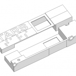
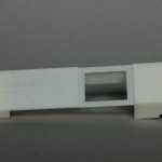
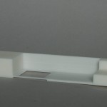
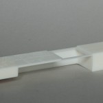
Fabrication has started in earnest. I decided to go with the most complicated piece first – possibly not the best approach but I reasoned if I failed to do this, the whole project would be off.
The first task was to produce some stock from which to machine all the pieces. I made a column from sheet styrene 160mm x 30mm x 20mm – big enough to make half of one quarter of the main body – this is about as big a piece as I can work on in one go on the mill. It was long enough to also include some spare material at the end that I could use for mounting the piece securely on the workbed.
A silicone mold of the column was poured and left to cure. In this I then cast a slab of urethane resin as my workpiece.
The first job was to mount the resin on the mill and then machine one surface completely flat (known as facing). This then becomes the bottom face and all subsequent operations are then guaranteed to be perpendicular or parallel to this face. The block was 20mm thick and the final thickness needed to be 16.7mm so I took off around 2mm at this time using a 3mm end mill. This was the first of several long, noisy and dusty operations! The process took around 30 minutes, milling off the resin manually layer by layer. Holding the vacuum cleaner hose as close to the cutter as possible as it worked sucked up the vast majority of the dust and swarf, but a fair amount still escaped, covering everything in a snowy layer!
Job 2 was turn the block over and reduce the thickness to 16.7mm. This and all subsequent operations were done via CNC. The data from the Sketchup drawings was exported to a series of DXF files which were then imported into CAM software. This allows you to generate the g-code instructions for the CNC controller that tell the mill where to go and what to do.
After watching it grind away for another 20 minutes, my piece was now exactly the right size on one dimension!
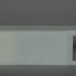
Job 3 was to engrave all the detail onto the front surface – the TARS lettering, the braille underneath and the panel lines. This was quickly achieved using a 45 degree “V” engraving cutter. I figured that it was best to do this first since everything else was going to take some time and I’d hate to mess things up on the final hurdle!
Job 4 was to create the recessed strip in front of the two screen holes which will hold some tinted material, and the two screen holes themselves.
I flipped the piece over and started on job 5 – removing the bulk of the resin inside the piece to allow for the display board. This was another long operation and nearly ended in disaster. By some miscalculation on my part, it ended up going deeper than it should – the recessed strip at the front should have ended up 1mm thick, but actually ended up being 0.5mm! Luckily it’s just about salvageable.
The last big operation was to remove the channel at the bottom of the piece. this is only really to allow the wires up from the battery back and in hindsight could have been a lot smaller ( = quicker to mill!)
2 small recessed were cut which will contain the magnets used to hold the whole assembly together. A half circular one at the top which will mate with the same in the other half, and a full circular one at the bottom side.
All that remained was to mill the outside dimension of the piece to free it from the excess stock. Well not free entirely – two small holding tabs were left, one at each end to ensure everything remained steady as the rest of the machining progressed – much like plastic sprue attachment points.. Once finished, these were cut through with a micro saw and the remaining nubs sanded flush.
Overall it came out better than I hoped but not entirely perfect. There’s a small bit of scoring on the sides due to the mounting not being secure enough which caused the piece to move during machining and also I think I was cutting a bit too fast, overloading the drive mechanics a bit. Nothing that won’t polish out. But it was a good learning exercise!
There is still more work to be done on this piece on the outside-side – more panel lines and holes for magnets but these have yet to be CAD-ed up.
