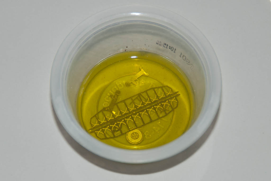
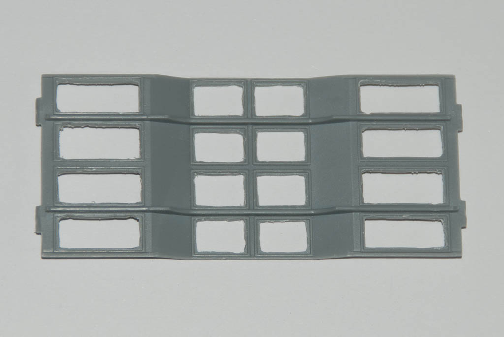
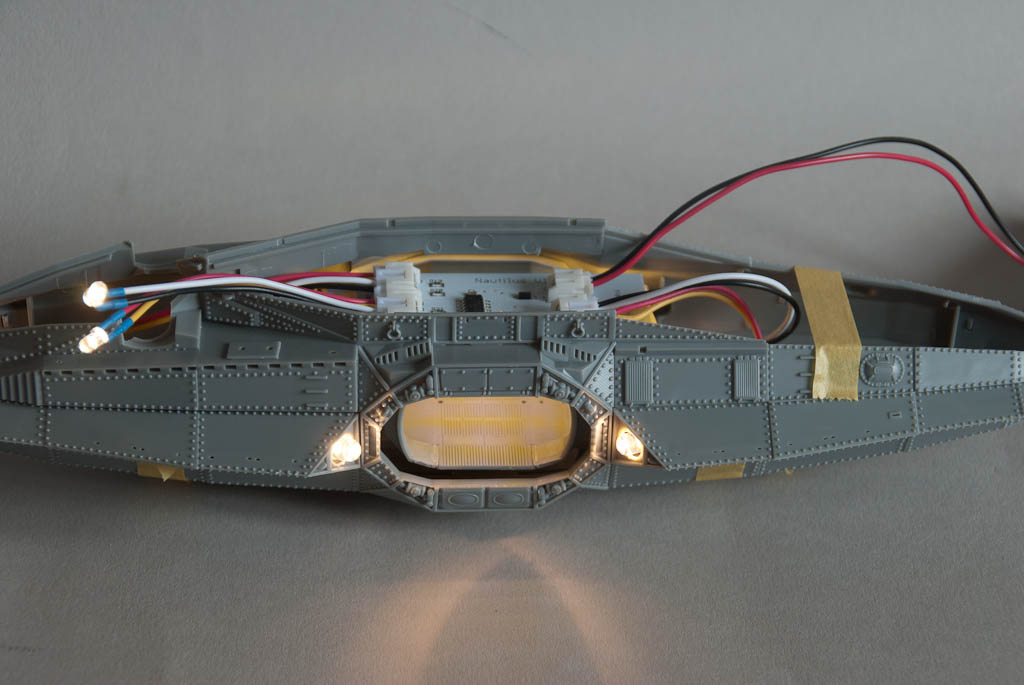
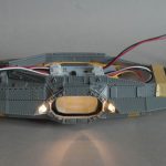
I’ve started work on an animated lighting module for the Pegasus Nautilus submarine. This kit features a detailed interior, which is improved even further by the ParaGrafix photo-etch detail set. This includes an additional interior for the forward wheelhouse as well as extra details for the main lounge/observation room. The ceiling of the observation room features 16 lighting panels, so I decided the easiest way of tackling this project was to design a module that had 16 LEDs mounted on the bottom that line up with these panels. After opening up the panels, the PCB will sit on top and shine through into the observation room with no messy wires. Part of the PE set includes some nice perforated panel covers which will improve the overall lighting effect.
Apart from the ceiling lights, there are 4 exterior spotlights, two on each side of the hull at either side of the big observation windows – obviously designed to illuminate the murkey depths. Finally an interior light is needed to illuminate the wheelhouse and one more for the searchlight mounted on the top of the vessel.
There’s not much the lights really “do” but rather than just be static I decided to go with a fairly simple system that turns the lights on and off in various sequences.
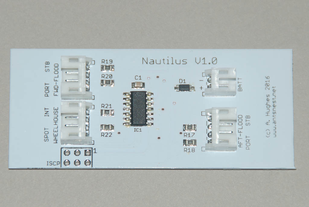
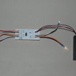
A quick circuit was drawn up based around an Atmel ATTiny84 micro controller – this has enough outputs to drive the ceiling lights as 4 strips of 4, 2 pairs of spotlights, port and starboard, the wheelhouse, and the searchlight. It’s small enough to fit everything easily on a PCB no bigger than the top of the observation room.
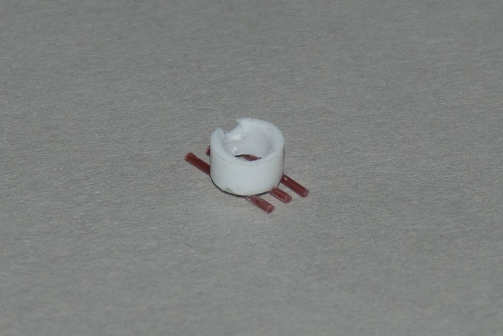
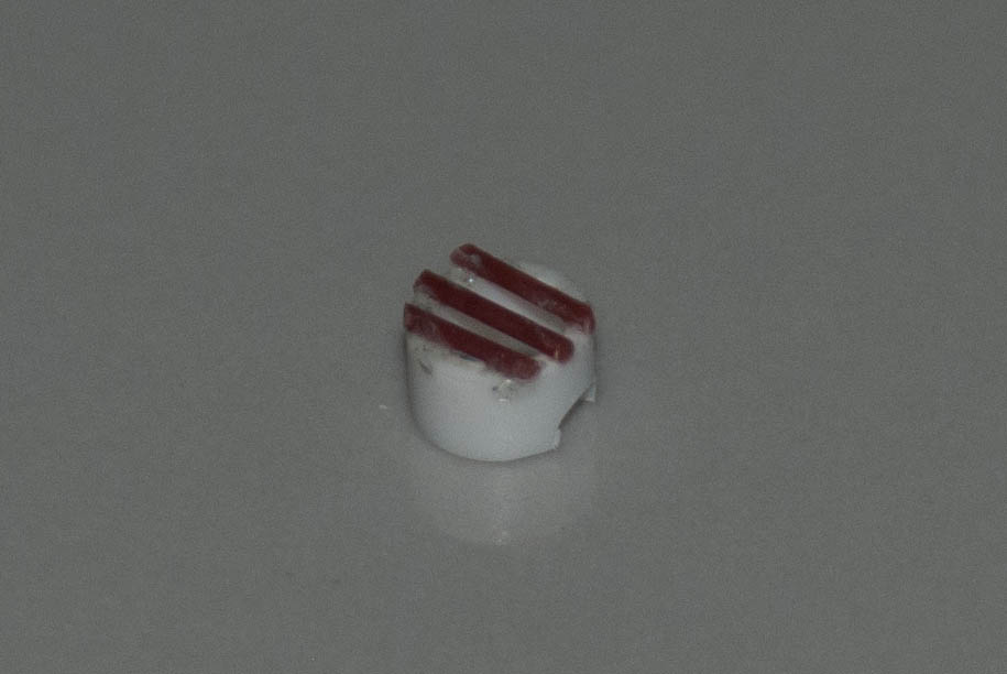
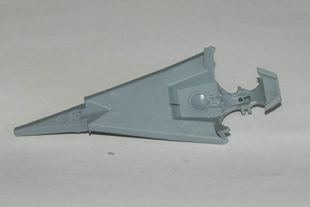
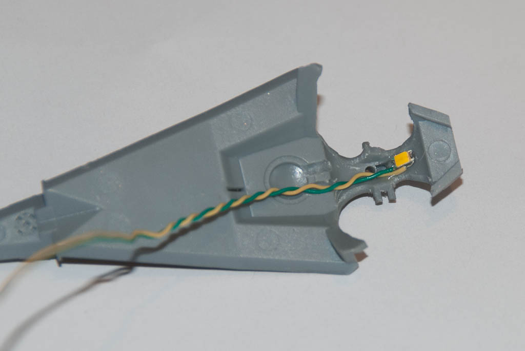
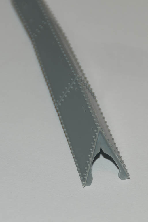
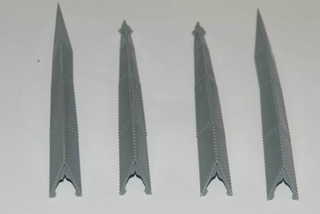
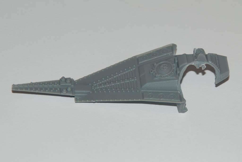
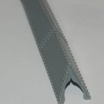
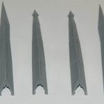
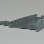
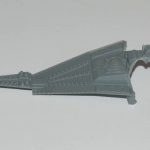
The four spotlights protrude from the ends of triangular wedge shaped strips that attach to the sides of the hull. I started off gluing the halves of each wedge together. A small end cap holds the clear piece representing the spotlight window. Normally this clear part must be attached before the end cap is secured in place due to the way it is partially covered by an alignment lip on each side. I wanted to keep the clear parts of until initial painting was completed, so I removed the lip overlap from the end of the wedge to allow the window to be dropped in later.
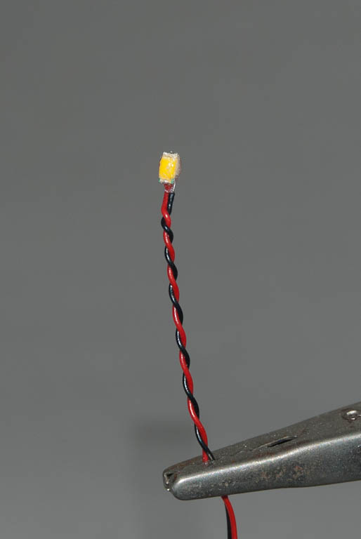
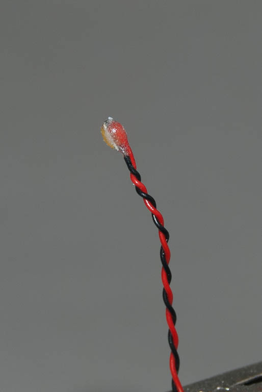
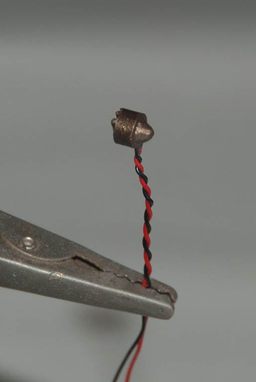
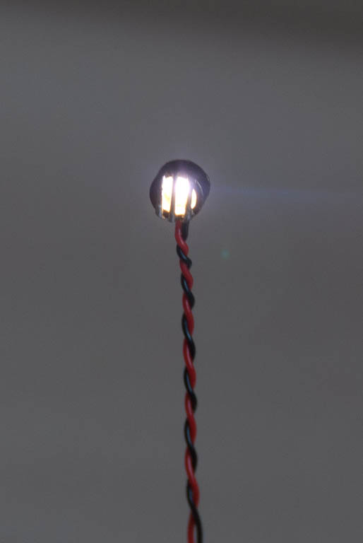
A 5mm LED fits quite snugly into the back of the window. The LED and wires will need to be fed through from the inside of the hull, so I opened up a hole in the side of the hull roughly behind where each LED will sit.
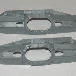
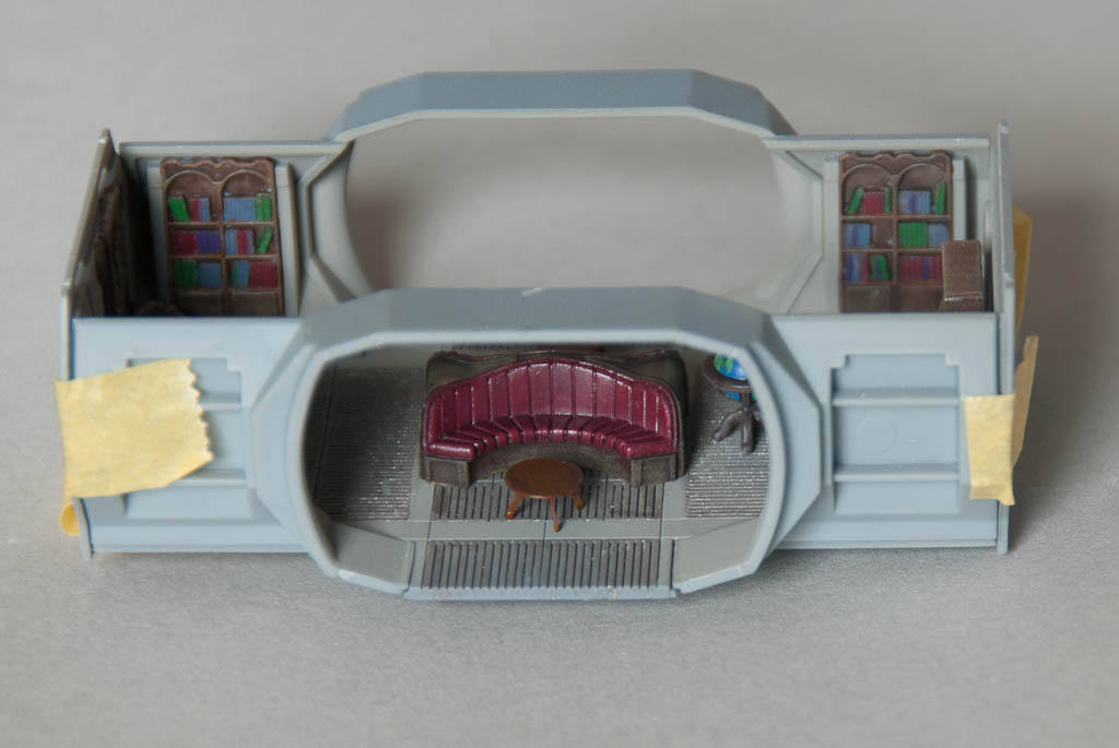
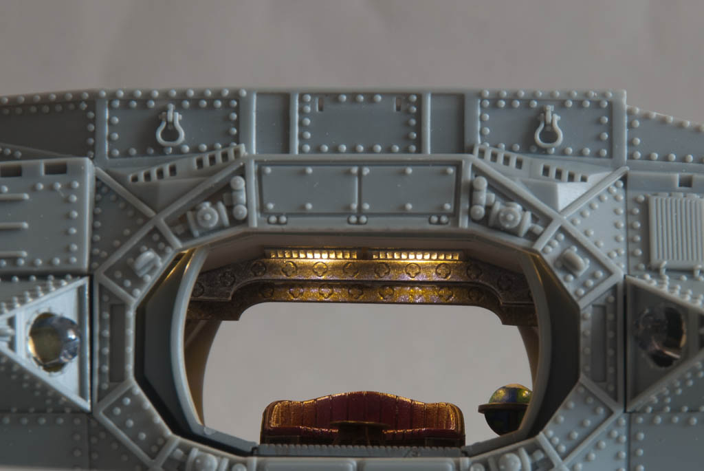
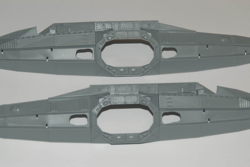
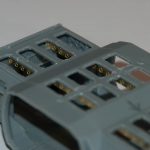
In order to see into the wheelhouse though the top windows, it’s necessary to open up the area that normally blanks these off from part C3.
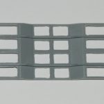
Opening up the light panels in the ceiling is quite a tedious job. I started by drilling 2mm holes around the inside of each panel, then cutting out the remaining plastic between the holes with a knife. The inside of the panel was then filed into a clean rectangle. You don’t have to be too precise here since the PE panel cover will hide any untidiness.
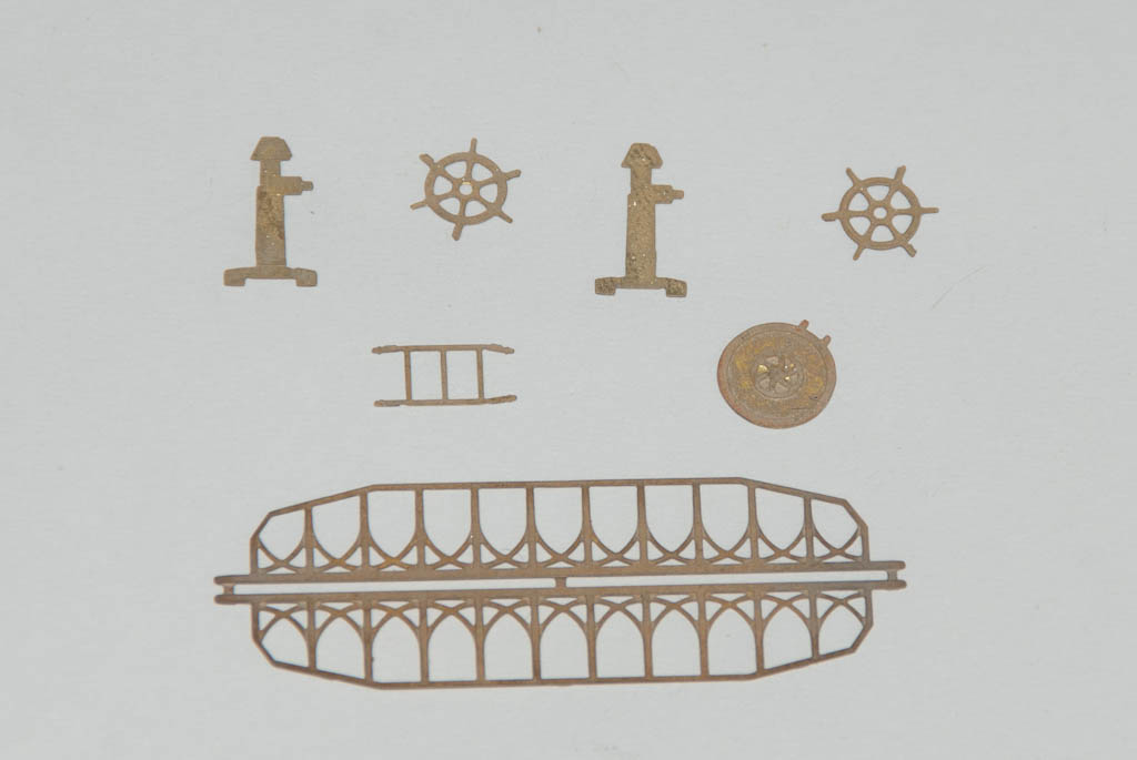
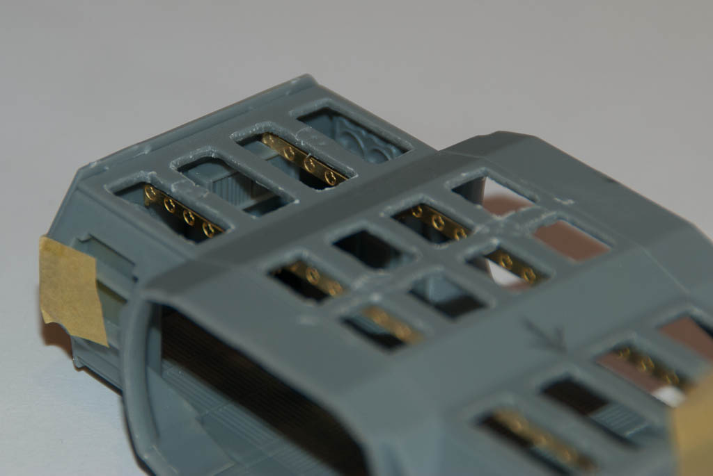
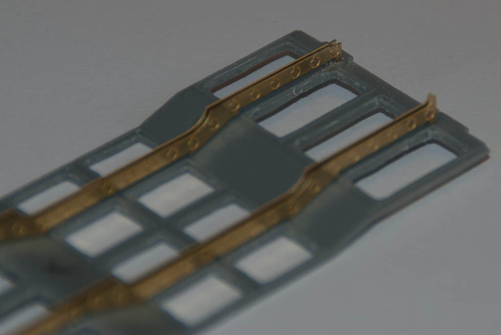
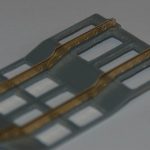
When fitting the PE crossbeam details, pay attention to the fact one side is about 1mm shorter to the other side (due to how the pipes of the organ on the back wall are arranged). Whilst doing a test fit after this stage I discovered a much larger issue – the detail end-pieces on the longer beam also foul the top of the bookcase on the other wall! There is no mention of this in the PE instructions at all. I had to file down the points on the end of the beam, and also file a 2mm wide slot into the top of the bookcase to get the ceiling panel to fit properly into the side wall lugs.
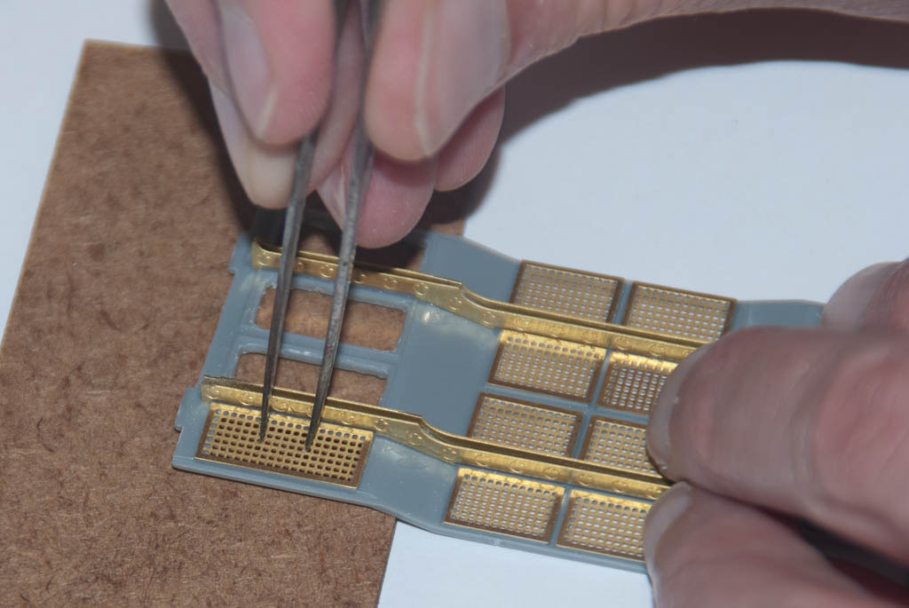
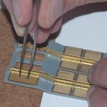
Attaching the PE light panel covers is quite fiddly. I found the best way was to put a couple of spots of CA on the raised lip of the panel hole, and then pick the covers up with needle-nose tweezers through a couple of the holes in the PE and then lower into place and hold until the glue grabbed. With the tweezers in the holes it’s relatively easy to ensure each panel is correctly positioned and square.
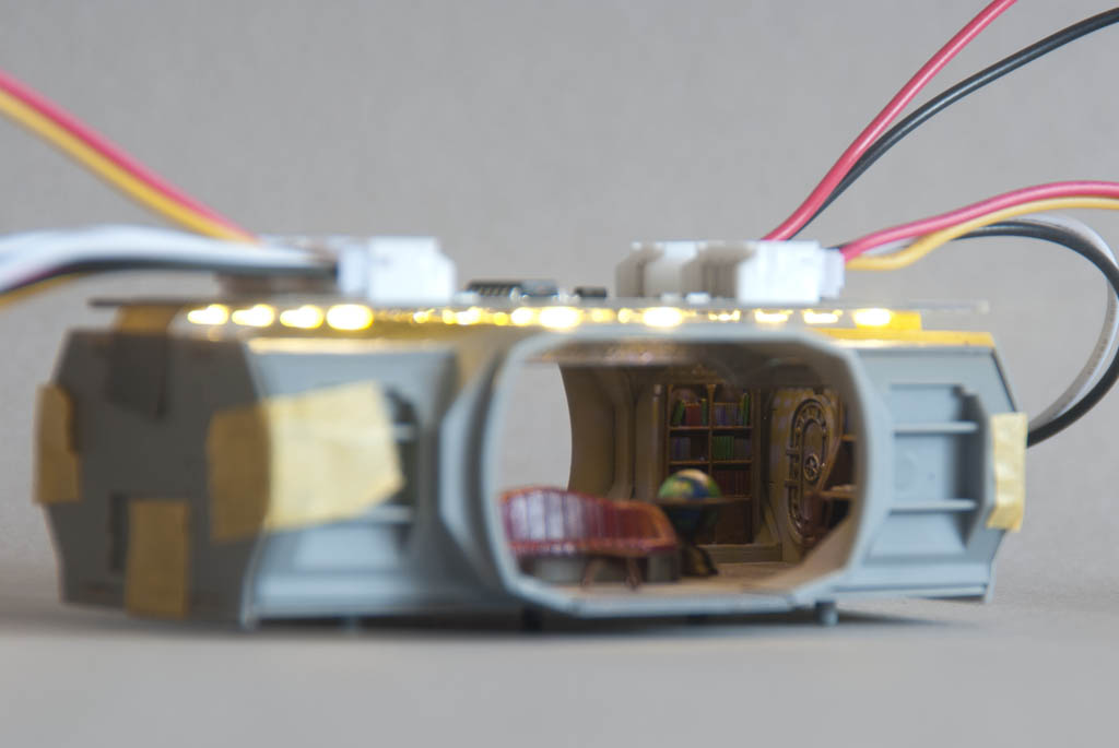
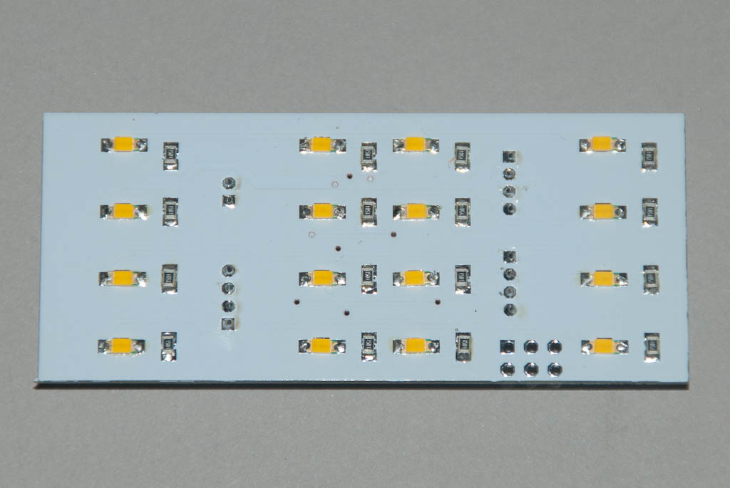
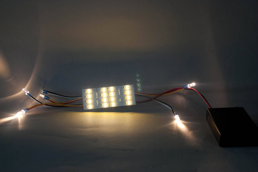
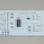
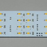
A PCB was draughted up and sent off for manufacture. I chose to go with a white solder resist coating rather than the traditional green as this will help spread the light inside each of the lighting panels. After about 2 weeks, a parcel of boards arrived and I set to work assembling one. With the exception of the LEDs for the spotlights, searchlight and wheelhouse, all the components are surface-mount types. The 16 observation room lights and their series resistors are on the bottom and everything else is on the top. Connectors were added for all the other LEDs – not really necessary but it does mean the board can be completely removed during assembly if necessary.
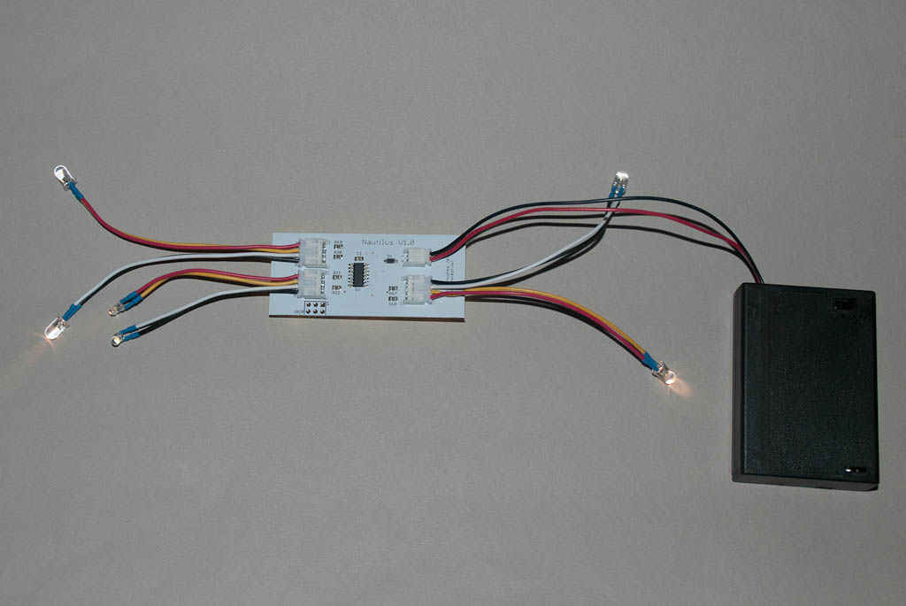
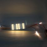
Once assembled, a small bit of code was put together to fade the lights up and down in a semi-random sequence and uploaded to the microcontroller. This will probably be tweaked a bit as the project progresses.
Part 2 >>