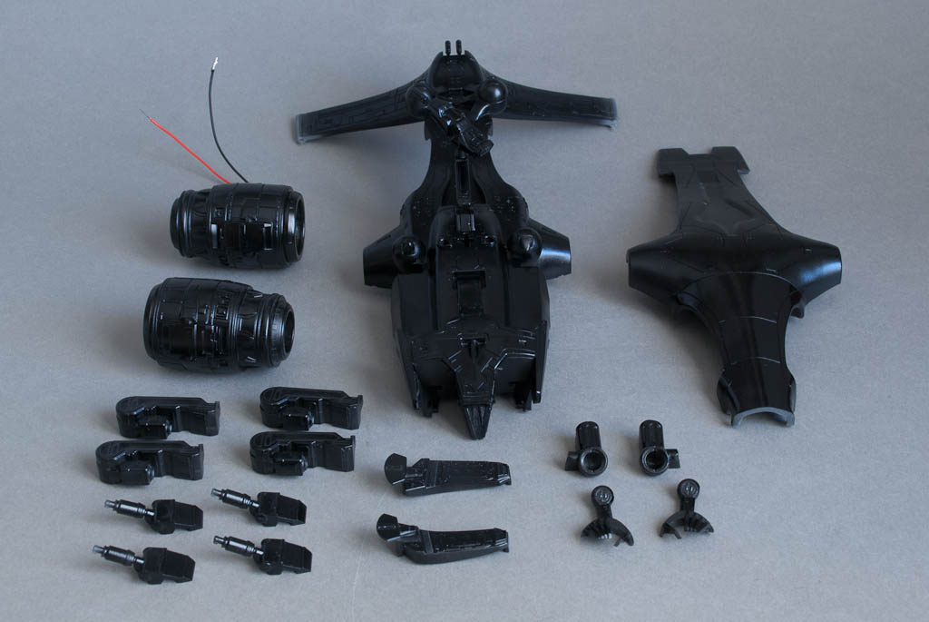
Pegasus recently released a styrene version of the Aerial HK from the Terminator franchise – a vinyl version was released by Horizon in the late 90’s but the kit itself was soft on detail and suffered badly from droop. I had one for many years but never got around to building it…
The Pegasus version is about half the size (1/35th scale) but much more detailed, and is a perfect candidate for lighting. There are three areas to tackle – the big searchlights at the front, the underbelly lights and the red/blue tail lights. The kit comes with clear parts for all of these which simplifies things considerably.
I decided to tackle the hardest area first – the tail lights. Each tail fin has a light on the front and back tops, red on the left and blue on the right. The clear insert provided with the kit is a straight bar that runs the length of the fin tip and protrudes at each side, but I needed separate pieces so that I could get the light inside somehow. Available space is very tight – too small for even a surface mount LED let alone one with leads so I decided to go the fibre optic route instead. With a bit of shaving to the inside of the fin pieces, it’s possible to get some 1mm FO up and out of the holes where the lights are. I was originally going to use the ends of the kit parts, cutting them off and then drilling a 1mm hole in the back to accept the FO, but in the end I decided to make some new ones from a bit of the scrap clear sprue – this way I could make them slightly bigger and more robust.

For each light, a piece of sprue was turned down to about 2mm dia in my lathe, and then the end was rounded off using sanding sticks. The 1mm hole was then drilled by hand using a pin vice to a depth of about 2mm – just enough to securely glue the light onto the end of the FO. I also warmed the FO over a candle and bent it to approx 90 degrees to relieve the stress of flexing it down the tail piece. Even 1mm FO is quite springy!

This was repeated for all 4 lights, and then the ends of each pair were secured together inside a short piece of aluminium tube. A slightly larger tube was glued over a 3mm LED (one red, one blue) so that the FO could be mated squarely with the end of the LED.


The front searchlights were next – the 2-part housings each had 2 locating pin/sockets on the inside (somewhat over engineered for such small pieces!) which were removed with a Dremel to allow space for the LED and wiring before gluing together.

The clear lenses for these lights conveniently have 3mm holes in already so it was easy to just push in a LED. The leads were cut down to about 5mm and bent up to allow the LED to sit snugly inside the housing once attached to the lens. The wires pass out of the top and just squeeze over the bulkhead into the main fuselage cavity.


The belly lights were the easiest – they just require a 3mm hole drilling through the fuselage where the lenses for these normally go, and a couple more LEDs popping in from inside.
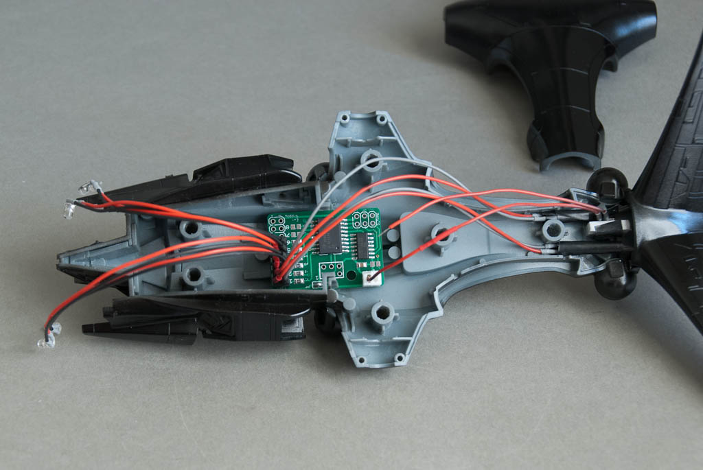
Originally I was going to wire all the lights up as static as this is how they appear in the opening sequence of T1, but in the end decided to jazz things up a bit. First I wanted the tail lights to blink like aircraft navigation lights, which would be easy to do with one of my generic controller boards. Then since the controller was going in anyway, I decided I might as well do something with the search lights too. I haven’t decided exactly what yet but will probably go through some sort of powering up – search – power down cycle…