Police Car Lightbar

One of the examples I made up for the original V1 LED driver was a police car lightbar to fit a 1/24th car kit (The one I had was an Lindberg Ford Crown Victoria). Whilst the PCB with the LEDs on fitted inside the clear cover of the kit, the driver board was way too big to be hidden anywhere in the car, and also required 5 wires to connect to the light board.

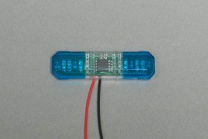
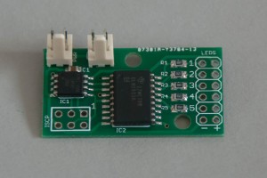
Having played around with surface mount components and various other Atmel microcrontrollers for a while I decided to see if I could get a complete driving circuit onto just the light board. An Tiny85 in a SOIC package was small enough to fit in the center of the board, and provides the 4 ouput ports required to drive the LEDs. It will run happily on the 8MHz internal oscillator, so no additional timing components are required, and will also run on 3v. A single CR2032 will power the board for a few hours and can very easily be hidden within the kit, or for a more longer lasting supply either 2 AAA’s or a single lithium CR123 will run it for much longer at the expense of a little more bulk.

Lightbar PCB inside kit cover

Lightbar With Cover

Lightbar in action
LED Driver Version 3

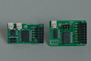
Version 2 of the LED driver is much smaller than the original V1 but at the expense of a little of the functionality – it only has 5 outputs instead of the original 8. While this is great for many applications, sometimes you need those extra outputs, which has lead to the development of V3.0.

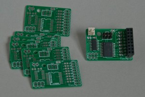
This restores all 8 outputs with only a 20% increase in the height of the board (dimensions are now 36mm x 25mm) and also boosts the number of inputs from 2 on V1 and 1 on V2 to 3. Additionaly it restores the ability to trigger a CPU interrupt from one of the inputs.

DSC_3183 DSC_3184

LED Driver V 2

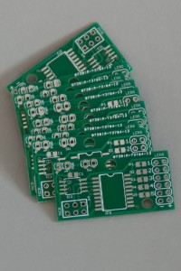
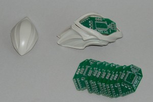
I’ve just received the PCBs for my next lighting project. It’s a slightly simpler in design but much simpler in build and considerably smaller and cheaper version of my generic LED Driver. This is designed to run off 3 – 4.5v and provides 5 individual ouptuts which are driven by the microcontroller via software written for each specific application.

PCBs

Complex flashing, fading and sequences can easily be implemented. One output can also be used as an input instead – a connector for a push button switch that can be uses to select different sequences for example.

LED Driver Assembled

The board measures just 36mm by 20mm and could happily run for several days continuously on just 2 AAA cells.


The First Cut….

.. is not the deepest, but it is the most nerve-wracking! After many test passes through air, I finally let the mill engrave some acrylic sheet… with relatively pleasing results!

If you can’t see what it is, it’s a skull & crossbones!

CNC Milling Machine First Steps

I bought a small Proxxon MF70 milling machine last year to help out with a few modelling jobs here & there, but also with the aim of converting it to CNC control (or rather CN control to be pedantic).

As an xmas present to myself I finally splashed out on a CNC conversion kit from www.ideegeniali.it which included the stepper motors, motor mounting hardware and motor controller electronics. I’m using an old PC I never got around to throwing away as the ‘brains’. The controller uses an old style 25-way parallel port connection so I had to get an extra PCI parallel card as most motherboards don’t provide these any more (even ones from 2005!).

I’m now starting on the very long path to undersanding how it all works, but a few days tinkering have got me as far as getting my first responses from the mill to some G-code which was really exciting!

Rather than actually milling something and making a mess all over my computer desk where it currently resides, I just inserted a pencil lead in the chuck and got it to draw instead.


Mohawk

I was very kindly given this Mohawk gremlin earlier in the year by a fellow Clubhouse member Stu – it’s one of the remaining two I was missing from my collection, for which I am eternally indebted!

After him sitting around on the shelf half-painted for 6 months, I finally sat down this week and finsihed him off.

And now the Mogwais are (almost) complete…


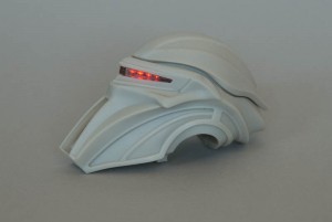
Cylon Centurion Lighting Done

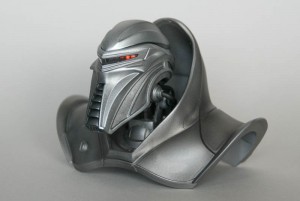
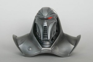
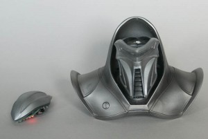
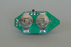
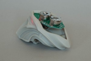
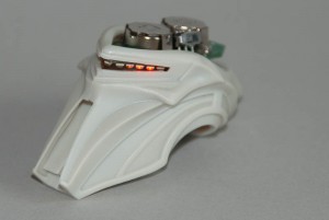
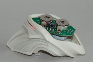
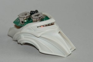
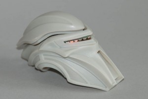
With just a little bit of modification to the original kit, I’ve now installed the lighting module into the Cylon. A single magnet holds the PCB into the lid, thanks to the metallic batteries and clips, and then another 2 magnets hold the lid to the head itself.

Once assembled, you’d never know the top was removable, but provides easy access to turning the unit on and off and changing the batteries when they are flat.

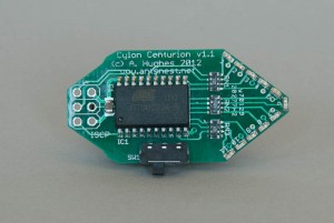
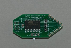
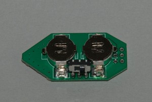
Cylon Centurion Lighting Module

I’ve been working on this on and off since receiving the Cylon test-shot and the first bunch of prototype PCBs arrived yesterday. This will be a completely self-contained module with onboard batteries that just drops into the head of the centurion – so no messy cutting, drilling or wiring!

There’s still some fine tuning to do, but it’s pretty close for a first attempt…


Video of the unit in action


Moebius Cylon Centurion – First Look!

Frank Winspur, Moebius CSO was very gracious in offering me a pre-release test-shot of the forthcoming Cylon Centurion kit in exchange for one of my Raider lighting modules! I was mainly interested in seeing how suitable this will also be for a lighting upgrade, but it’s a kit I’ve been waiting for anyway for a long time.

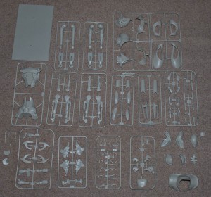
The kit arrived yesterday and my first impressions were wow! It’s big! Second impression was wow! There’s a lot of parts! it’s going to be fun putting this together as it was just polybagged with no instructions, but hey, we all love a challenge!

The head does have a bit of space inside, but not much. The eye slot is about twice the size of the one on the Raider so will need more and/or larger LEDs which may make the assembly of a module somewhat easier. The very top of the head serves as a nice hatch into the headspace so it should be possible to assemble most of the kit beforehand. I have a few ideas about the batteries. Stay tuned.

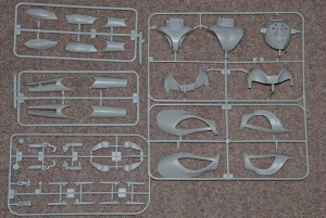
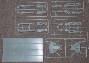
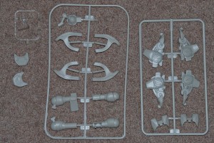
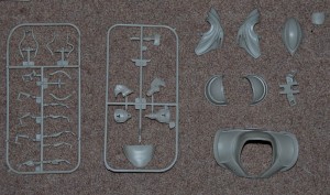
Here’s some pictures of the sprues – the base is 10″ by 6″ to give you an idea of the size.