Gerty from “Moon”

One of the best films of 2009 was Duncan Jones’ debut Moon, not least because it featured some high quality physical model-work. I’ve already built the SRS kit of the Lunar Rover, but now a kit of Gerty the computer is also available from Steve Howarth, the model shop supervisor on the film, and builder of the original props!
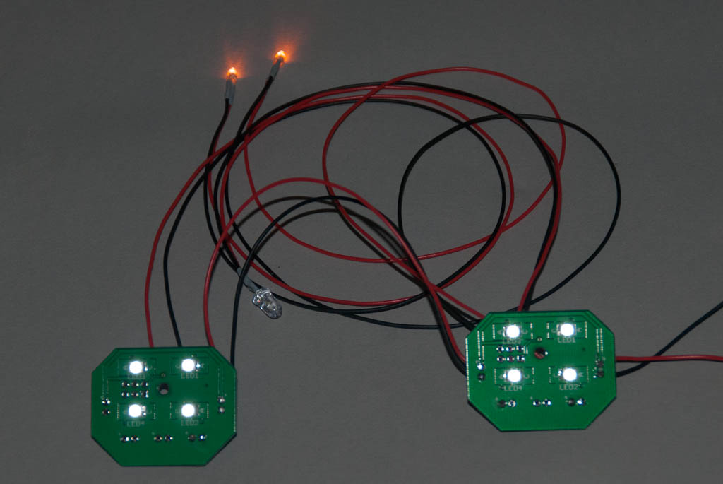
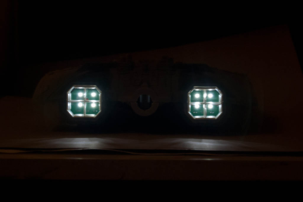
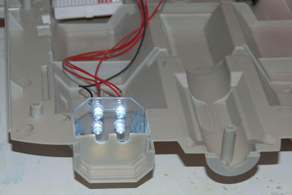
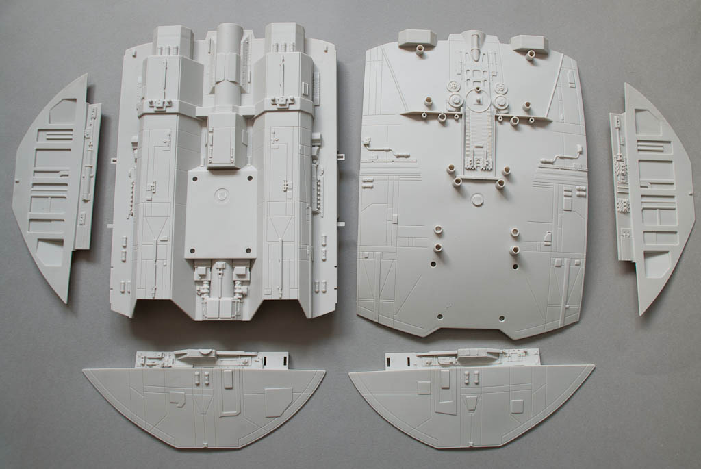
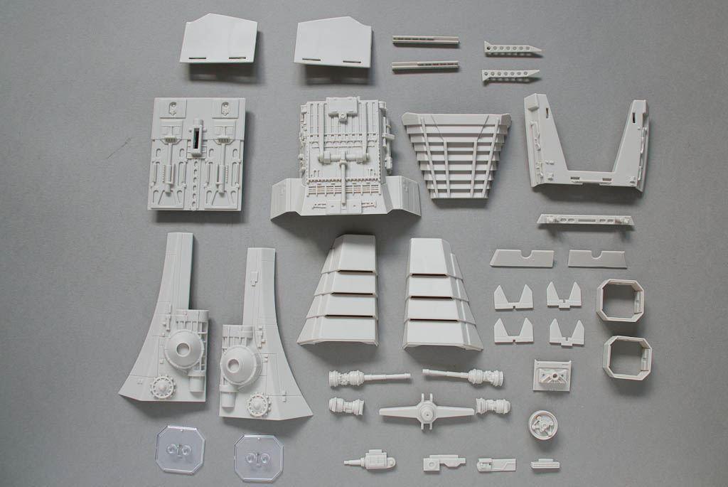
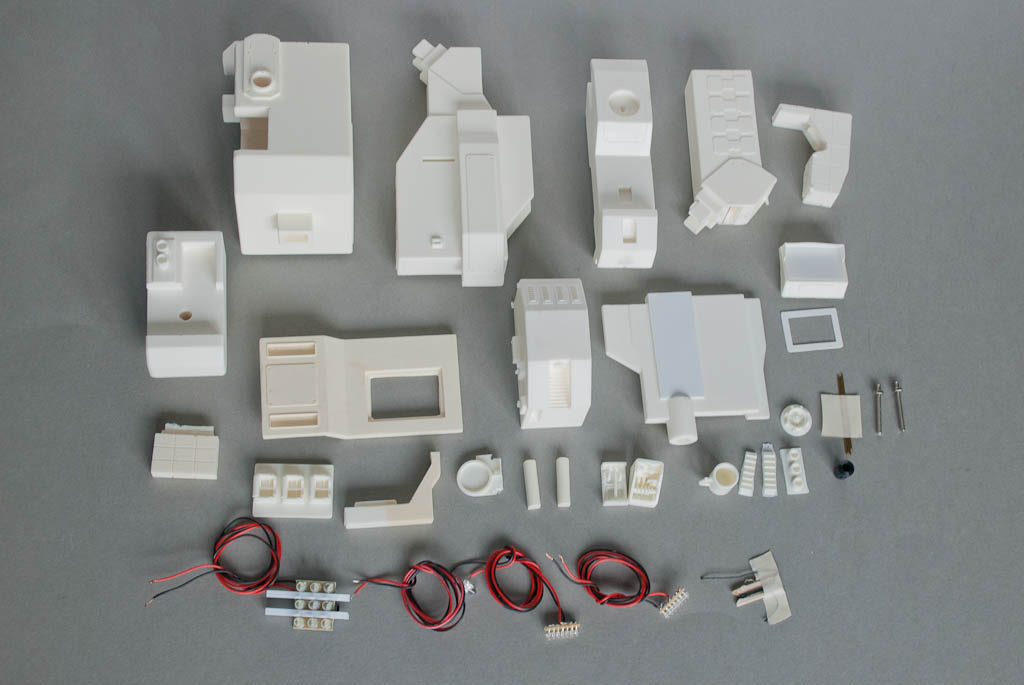
This is a 1/6th scale exact replica and comes in 24 resin pieces, as well as some LED assemblies for the strip lights, Gerty’s eye and a backlight panel for the main screen. To complement this there is a selection emoticons colour printed on acetate to insert into the screen to bring Gerty to life. There is also some brass wire and foil for extra detailing, some printed Post-It notes as seen in the film and finally a comprehensive set of decals – of which there is 3 copies of each to cover any mistakes in application.
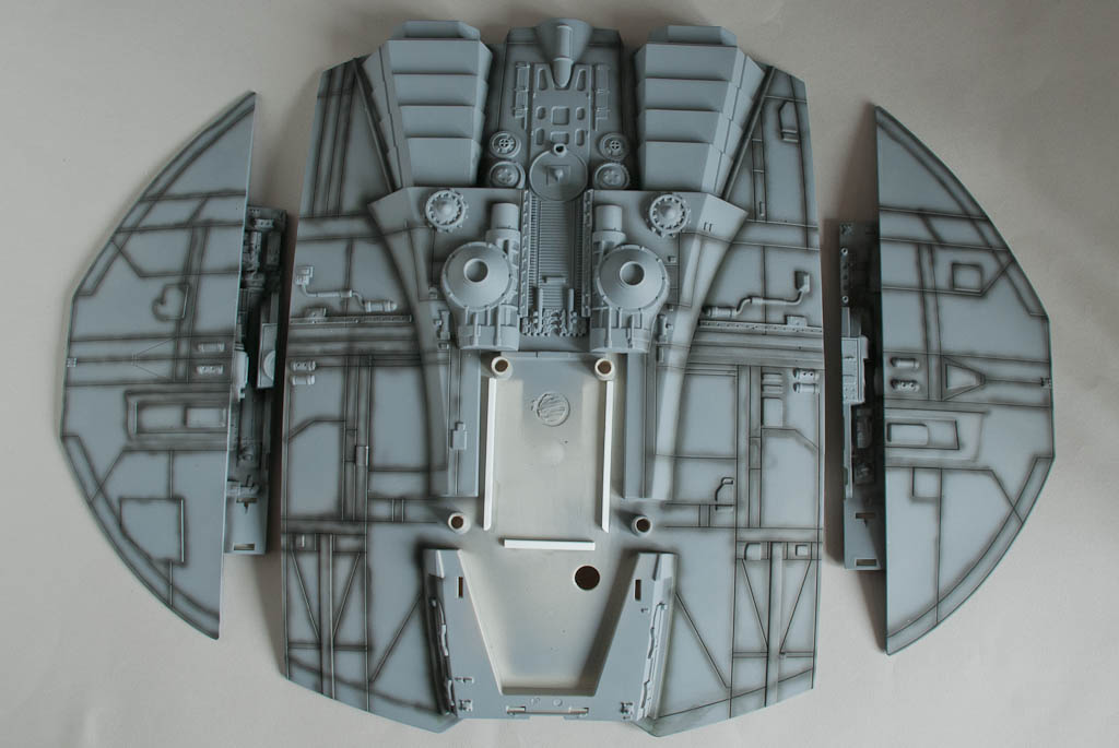
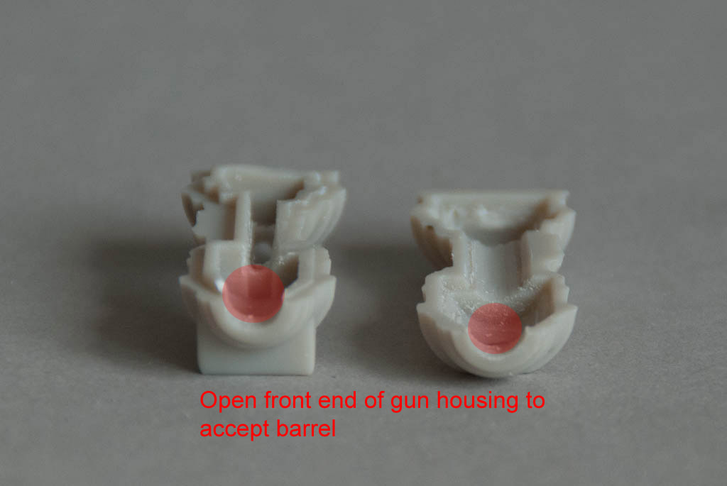
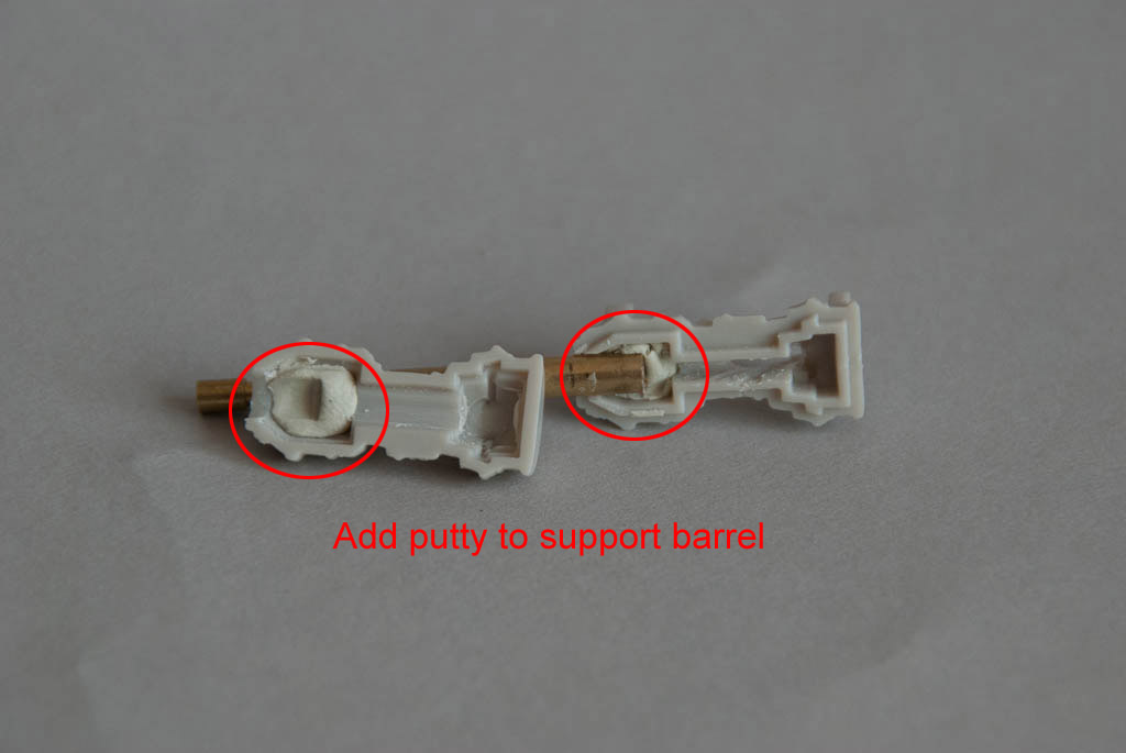
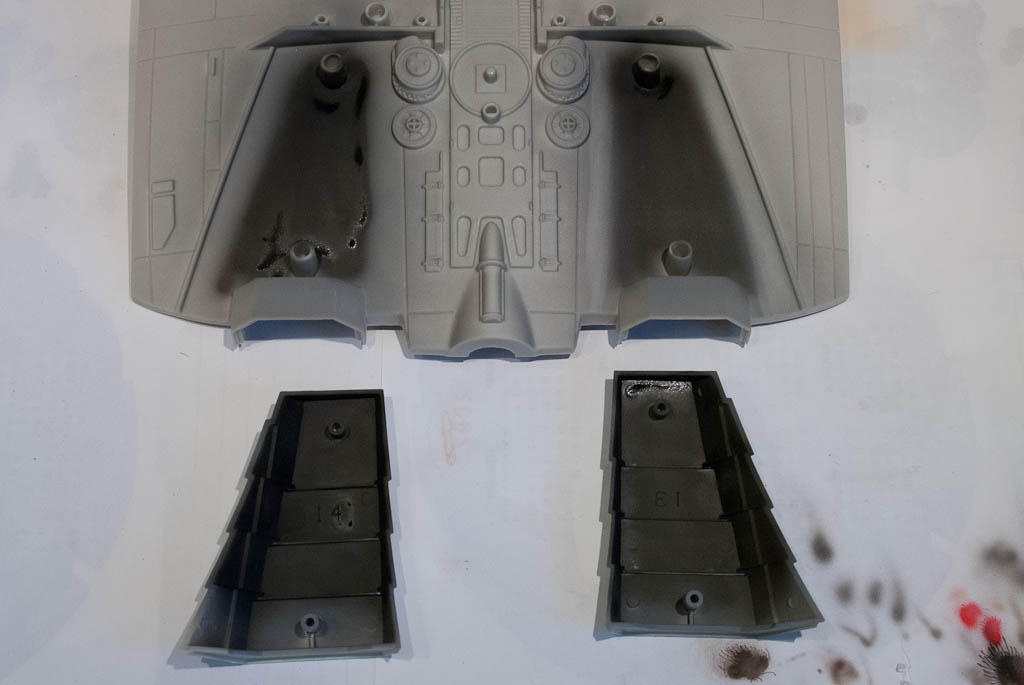
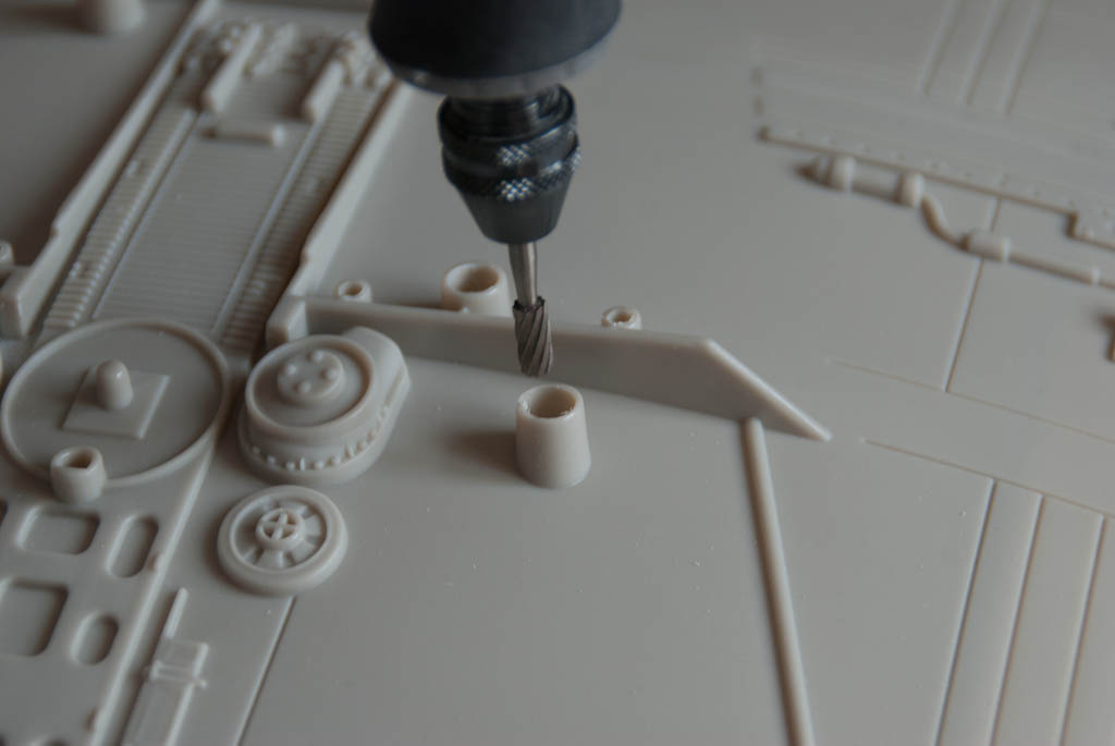
The resin is of good quality generally but there were quite a number of pinholes that needed filling, particularly on some of the edges. Filling is fairly straightforward but did take quite a while in the end to get them all. It’s sometimes easier to drill out a tiny bubble with a 1mm bit just so you’ve got something a bit larger to squish the putty into.
Gerty bits
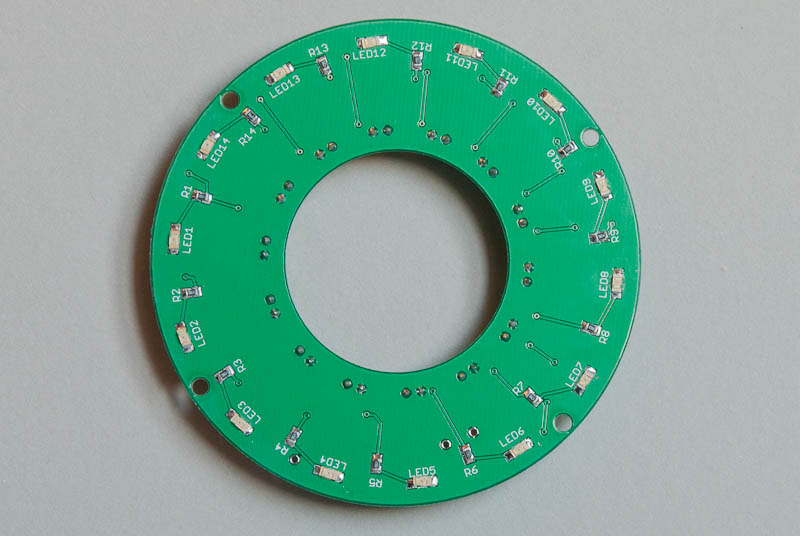
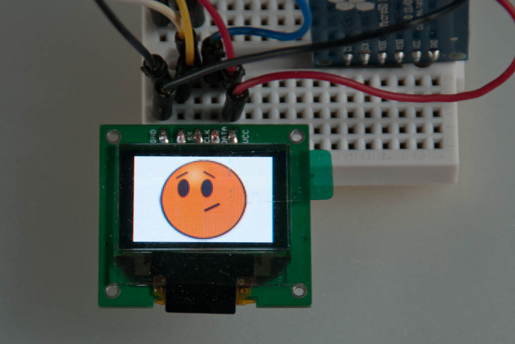
It would normally be quite a straightforward build – fit of the parts is good and can be painted beforehand in most cases, but I decided to go a little bit further and try and replace the screen with a fully functional OLED one, driven by a microcontroller and able to show the full range of Gerty’s emoticons.
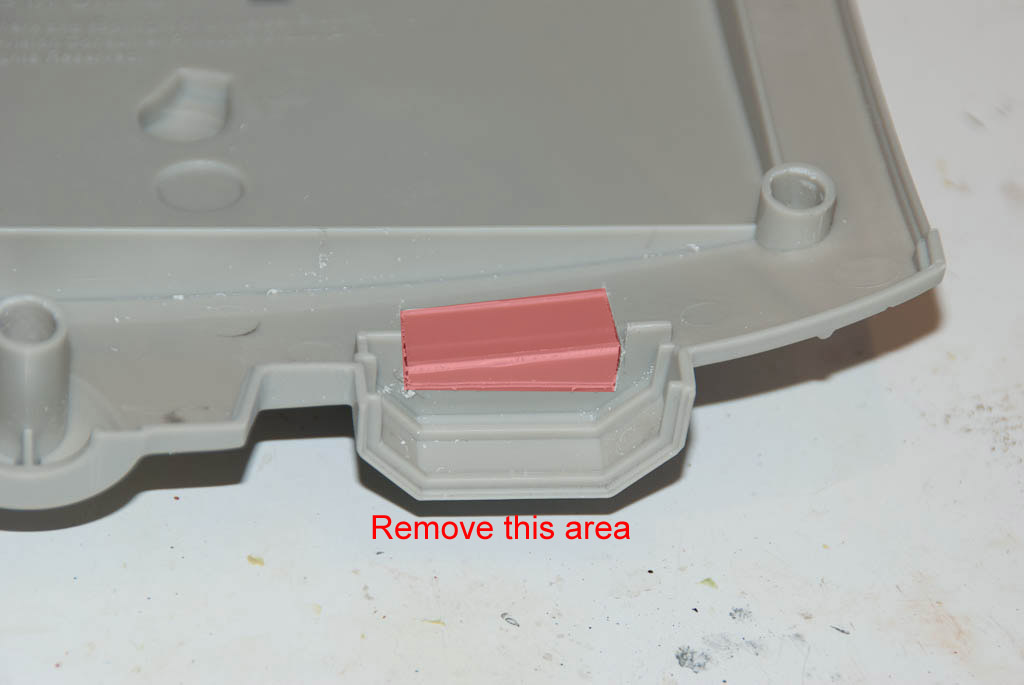
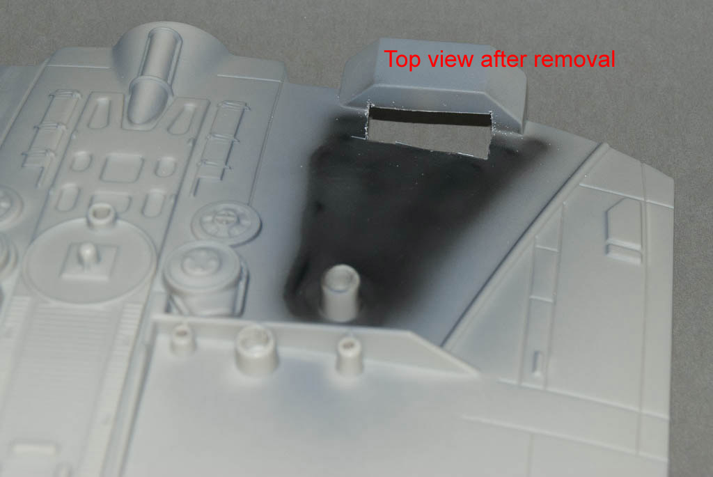
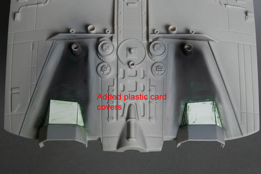
The kit screen is almost exactly the same side as a 0.96″ colour OLED device available from Digole.com – the active area is just marginally smaller, but it’s good enough. The biggest problem is that it comes attached to a larger PCB containing the display controller which means it’s not going to be a drop-in solution and some surgery will be required to get it into place. I think I will need to completely remake the surround & shade from scratch to accommodate it, but this should be a relatively simple job in plasticard.
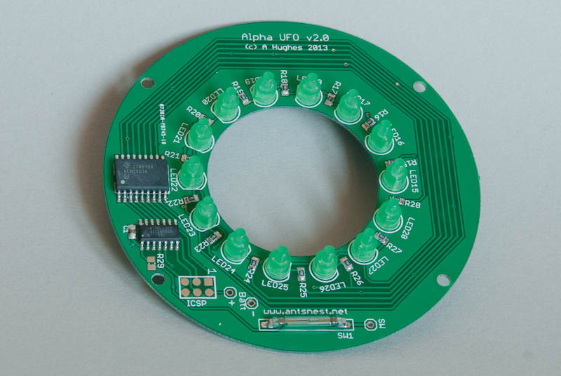
The display controller communicates over a serial interface which means it’s very simple to connect to a micro controller. It has a resolution of 96×64 pixels with a 65k colour depth – not huge but even at this size, the data for just one emoticon would nearly fill the available flash memory of the microcontroller. I want to have all 11 emoticons available, plus a “boot” screen so additional off-chip storage in the form of a micro-SD adapter is also required. Luckily this uses the same serial interface so again connectivity is kept simple.
Gerty Bemused
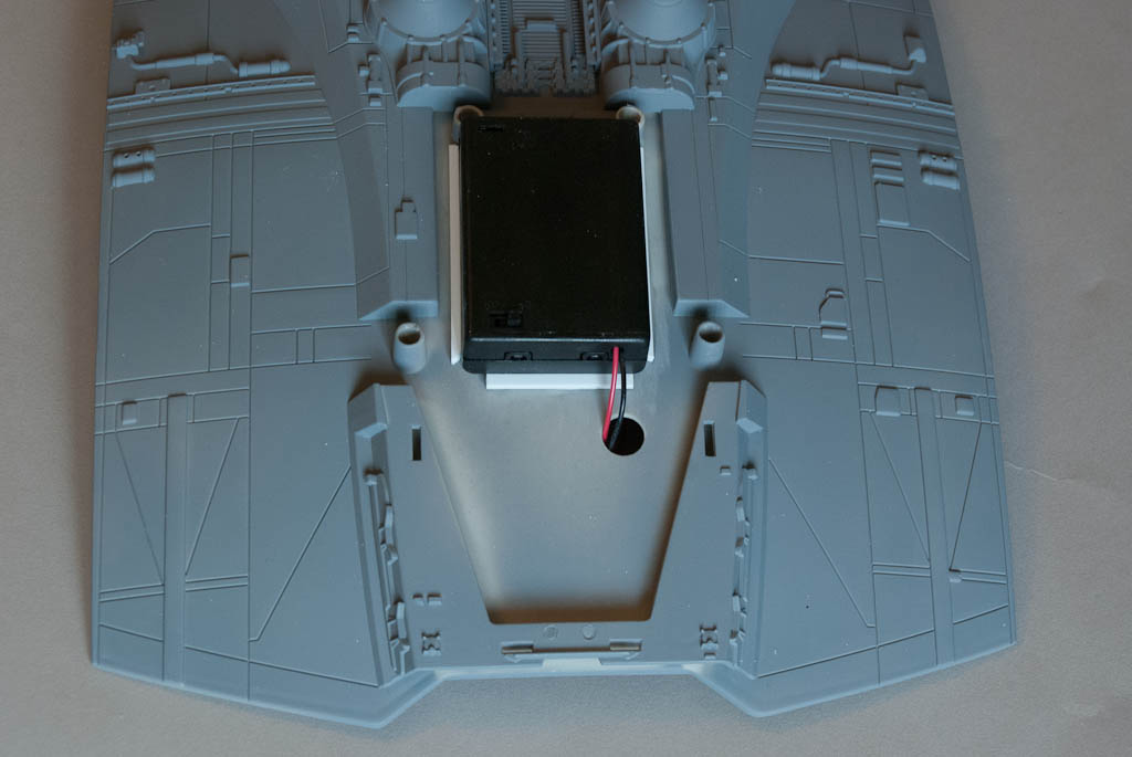
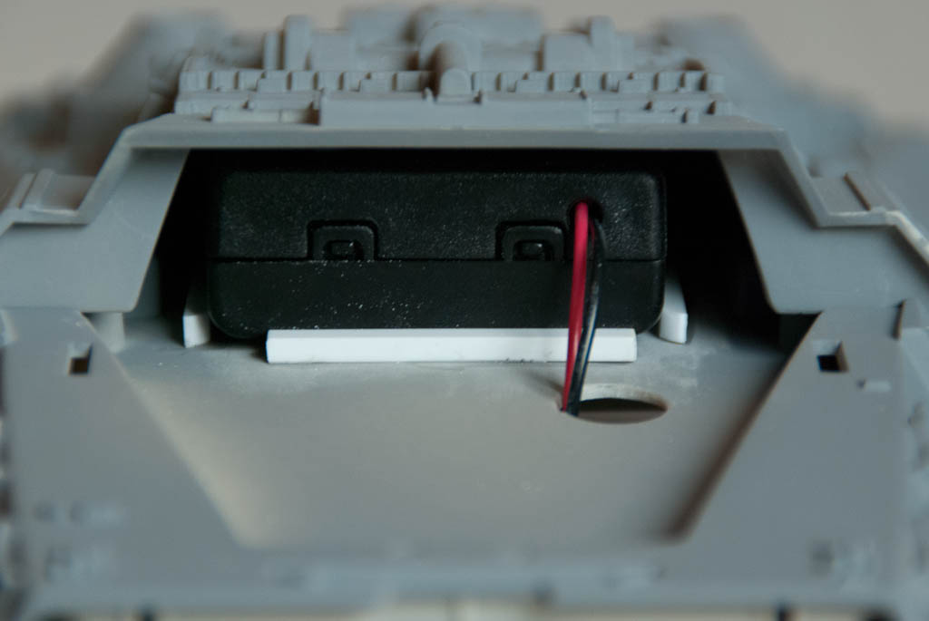
There’s plenty of room inside the main body behind the screen for all the electronics, but probably not the batteries too. This probably isn’t too much of a problem as Gerty is designed to be suspended from above, so will need some sort of corridor section to hold her (him?) anyway which will probably give ample battery storage space.

Part 2 >>

TOS Cylon Raider Pt 7

<< Part 6

A flurry of activity to get this finished in time for a show last week. After putting it off so long I finally had to fix all the electronics in place and glue the fuselage together – the point of no return – so that I could then tackle the seams this would create – and these were probably the worst in the whole model. Underside front and back there is a recessed lip, which was relatively flush, but still took quite a bit of putty to fill. Then there were the seams down the sides where the wing tips connect… This took considerable putty-sand-repeat until the finish was satisfactory, hampered to some extent by the wing tips having to be partially connected due to the fibre feeding the guns. In hindsight it would have been much easier to leave all of the wingtip and gun assembly until after the fuselage, but there we go. All the puttied areas were touched up with the base grey and then weathered down to match the surrounding areas.

It was then time for the final lighting test. Any problems now and I would be stuffed. Headlights – check. Underside lights – check. Engine ramp up – check. Guns – only one firing! Oh no! I’m stuffed! Disaster! Anguish! Panic! Depression… This was the worst case scenario. I had to go back past that point of no return again! It would be impossible to seperate the two halves without destroying the model, but there was one glimmer of hope. There is a 3″ x 2″ panel on the bottom where the stand is supposed to attach – if I could remove that, I could cut a hole underneath and hope to see what had happened. However because the stand attached to the panel, I had glued the panel down really really well. After much gentle prising and getting nowhere I was getting more depressed and desperate and started to pull harder and harder. Finally with a loud “pop” one end came loose, which allowed the insertion of a steel ruler to help lever up the panel until finally the joint at the other end gave way just before the plastic itself did!

The next task was to cut open the belly without risking even more damage to the wiring inside. Using a panel line scriber I slowly scribed out a section, round and round until the plastic was just cut through and the whole piece could be lifted out.

From there it was easy to see the problem: one of the fibres had come loose from the tape binding it to the LED – almost certainly as a result of all the jiggling about of the wing tips as I was fixing the side seams. This time I glued the fibres into one end of a tube with some clear epoxy, and glued the LED into the other, before binding it all up in tape again. Nothing is coming out now!
DSC_4739
I made an inner lip around the hole with some strip strene for the piece I had cut out to sit back against, and then glued the panel back over the top – lightly this time just in case I ever need to get back in again. Having already tried the model on the stand, there was no way it was ever going to stay on that, it’s just way too wobbly. Instead I think I shall make a cradle from clear acrylic at some point..

So here we are – finished!
DSC_4748 DSC_4754 DSC_4753

DSC_4752DSC_4755

TOS Cylon Raider Pt 6

<< Part 5

Made a lot of progress recently but forgot to take many pictures along the way! After pre-shading the panel lines on the main assemblies, A couple of light top coats of light grey were misted on, allowing just a hint of the shading to show through. The various darker grey panels were then masked off and sprayed – I kept these just a shade darker than the base colour so that the contrast is not too high.

A liberal coat of dark dirt wash from Flory Models was then brushed over everything, working well into all the nooks and crannies and then left to dry. These are great water soluble washes that are very easy to use and provide great results. Once dry, you just wipe off the excess with a damp cloth or sponge leaving just a hint behind that really makes the details pop out.
DSC_4725DSC_4726

Next came the masking of the black stripes on the wing tips. This would be a very simple operation to do with tape were it not for a couple of greeblies that have to be masked across. I used4mm tape for the most part, and then small bits of 2mm tape over the lumps and bumps. These were then extended with wider bits of Tamiya tape I had left over from a previous job (I find it’s very easy to reuse Tamiya tape several times before there’s any sign of the adhesive giving out). The straight stripe on the underside were also masked off at this time.

A not-quite pure black was then misted over in a few light coats to minimise the chance of seepage under the tape. The results were good, and probably less hassle than tying to do this with decals given the uneven surface.
DSC_4727 DSC_4728
There was one slight problem – when I removed the tape, it also removed some of the wash that was trapped within the grain of the grey topcoat resulting in faint but noticeable lighter strip on the outside of the stripes as you can see in the picture. A bit of rubbing along the edge and another application of wash managed to reduce this right down again thankfully!

Part 7 >>

TOS Cylon Raider Pt 5

<< Part 4

The wing tip halves were glued together and clamped all around the edges to ensure correct registration while the glue set. These seams then required a number of iterations of putty-sand-prime until all traces of the seam had been eradicated. The guns were also glued together and the seams addressed on these too.

DSC_4548

In some shots of the Raider in flight, and on at least one of the studio miniatures, there are additional lights visible on the underside, on the outside of the channels that run from the intakes to the engines – these appear to be mounted in small reflectors recessed into the fuselage. Using a short length of 10mm dia rod, I machined up a couple of these which are glued on the inside of the fuselage and hold a 5mm LED, also driven by the controller PCB.

DSC_4613 DSC_4615 DSC_4616 DSC_4617

A few strips of styrene were added to the fuselage top to hold the battery box in place – this slips up under the centre console quite happily and the styrene stops it sliding around, but still allow it to be pulled forward for switching on/off and battery changing. A hole was drilled just in front for the wires to pass down into the electronics inside.

DSC_4610 DSC_4612

When the 2 halves of the fuselage are placed together, the small “V” tabs on the top half are quite badly out of alignment with the bottom, protruding a couple of mm at the ends. The wingtip sides cover most of the rear tabs, but the front ones remain visible. I decided to cut these tabs off the top half completely, and then just fill in the gap on the bottom half with some plastic card – it was far easier this way to get the whole thing flush and smooth.

DSC_4630

Whilst waiting for some other bits to set, I decided to start doing a bit of pre-shading of the panel lines with black over the grey primer coat. This looks quite extreme but once the top coat goes on, most of it will having been covered up again, leaving just a hint of depth.

DSC_4619

A quick final test of all the lighting in place

DSC_4662 DSC_4668 DSC_4669 DSC_4670 DSC_4672

Part 6 >>

TOS Cylon Raider Pt 4

<< Part 3

The guns are to be lit using 1.5mm fibre optic, connected to the gun LED inside the fuselage. The guns are moulded in 2 halves, but one half has the complete solid gun barrel which makes it much more difficult to hollow out than if it was also in 2 parts. It could be possible to carefully drill out the centre of the barrel but I decided it would be much easier to make new ones from brass tubing. The barrel has 3 different diameters along it’s length – I found that brass tube in 3/32″, 1/8″ & 5/32″ is almost an exact match for the kit barrel and each section of tube slips over the next smaller diameter perfectly. All the bits of tube were cut and assembled into the new barrels with a touch of superglue. I made them 1/4 longer than the protruding bit of the kit parts so that they could be embedded inside the gun body.
DSC_4549
The plastic barrels were sawn off and a 5/32″ hole was opened up in the end of the guns – I just used a round file on each half until the hole was the right size. I added a small ball of putty inside the front of each body half, inserted the brass barrels to the required length and then squeezed the whole assembly together, making sure the barrel protruded straight out and was not drooping, then gently separated the body again and put aside for the putty to set.
DSC_4581DSC_4578DSC_4577
The 1.5mm fibre optic is the perfect size to fit inside the gun barrel but because it is quite thick, it is not very flexible. This creates a few issues trying to get the fibre into the gun. It needs to come from the main body, into the wing tip section, and then up through the gun mounting peg and into the barrel. Due to the inflexibility, it’s necessary to cut angled slots in the gun body and mounting location of the wing tip so that the fibre will pass through more easily without tight bends. I started cutting a slot in the bottom gun body piece and then widened and angled it using a thin round file – the goal was to get as shallow a path as possible up into the body.
DSC_4585DSC_4584DSC_4583
Similarly where the rear mounting foot fits into the hole in the wing tip upper section, I created another angled slot to match up. When the 2 pieces are together, the fibre can then pass up from inside the wing tip to the gun body with as little bending as possible, yet still be almost totally invisible from the outside.
DSC_4541DSC_4543
To get the fibre from the main body into the wing tip, a hole is needed in each. A suitable place was selected in the side of the wing tip and a slot opened up with a file. Holding the wing tip up to where it attaches on the main body, it’s easy to mark where the corresponding hole needs to be.
DSC_4535DSC_4538DSC_4539
Finally a check that everything lines up – the fibre goes through the wing tip side, up into the gun body, and out of the barrel.
DSC_4582

Part 5 >>

TOS Cylon Raider Pt 3

<< Part 2
Not much progress recently due to having been away on holiday, but the first batch of PCBs for the lighting modules have just arrived.

DSC_4508

DSC_4509

Looks like a good fit!
DSC_4507

Update!

Modules assembled with surface mount components. An Atmel ATTiny84 microcontroller drives the flickering for the engine LEDs plus a pulsed laser gun effect.

DSC_4510

All wired up to the battery, static headlights and single LED for laser (this will be piped to the guns via fibre optic).

DSC_4519

Finally a quick test in the dark with the modules inside the Raider body.

DSC_4511

Part 4 >>

TOS Cylon Raider Pt 2

<< Part 1
Work started in earnest at the back end – you could see a bit of grey plastic through the louvered engine farings so I decided to give the body underneath a quick dust of black, and also on the inside of the farings too.
DSC_4025

I started mocking up a 4 LED arrangement for the engines to test for alignment and dispersal and it was only then it actually clicked that the top half of the engine ‘tube’ does not continue into the body as it does on the Monogram kit. It’s screamingly obvious when you look at it, but I just failed to notice. Because the lights are to be mounted deeper inside the fuselage, this needs some modification to prevent the light being blocked. So it was out with the razor saw to remove a section of the moulding and then a new inner cover was made from sheet styrene – you don’t see this bit, it’s just to prevent light from leaking out of the louvered covers. This was also painted black for completeness. The mounting peg at the read of each faring also had to be removed, but the remaining one is more than adequate for locating the pieces when the are glued down.

DSC_4041

DSC_4043

DSC_4045

DSC_4046

DSC_4050

DSC_4061

The position of the LEDs and the shape of the PCB were finalised and send off for production.

The inside of the engine tubes were given a coat of primer to help with light blocking – another coat may be needed, but the majority of the light is focussed straight out so that may be good enough.
DSC_4058

Moving round to the front, 3mm holes were drilled into the corners of the front bulkhead detail (29) to accommodate 3mm LEDs for the headlights. In addition, the area directly behind these holes in the corresponding forward cabin part (10) was opened up to allow space for the back of the LEDs. Finally another hole in the back of each arm of part 10 was made for the headlight wiring to exit and be connected to the electronics.
DSC_4067

For the cockpit hatch, a small 3x3x12 magnet (I just happened to have lying around) was glued in under the front louver. Two 3mm dia x 2mm round magnets were recessed into the top of part 10 so that they lined up with the magnet in the hatch. This combination holds the hatch in place securely yet it can still be removed.

DSC_4019

DSC_4068

Part 3>>

Moebius TOS Cylon Raider

Moebius have just released their 1/32nd ‘Studio Scale’ Cylon Raider kit from the original BGS series. For some reason this pancake has always been one of my favourite sci-fi ships. I still have a built-up Monogram version that was released in 1979 – one of the very few models that remains intact from my childhood that didn’t get blown up, burnt, broken or bashed into something else many many years ago!

DSC_4011The first and obvious thing to note is the kit’s size! it’s about double that of the Monogram kit and looks very imposing. It’s much more accurate to the studio miniature, featuring recessed panel lines and more detail particularly around the nose, tail & engines.

 DSC_4012You get 49 pieces, including 2 clear engine inserts and a clear stand – a scaled up version of the regular Moebius BSG stand. Parts are generally moulded well although the detail is somewhat soft by modern standards – it’s certainly not up to Fine Molds standards, and even a Revell re-pop of the Monogram kit looks crisper.

There are a couple of small sinkholes at the front of the top fuselage that need filling but that’s it. Fit of the parts is pretty good with a few issues:

  • DSC_4013Many of the larger parts are secured by peg and socket arrangements – these are tight enough to hold the model together without glue but can actually prevent some of the parts mating together completely unless squeezed hard. Using a 4mm end mill in my Dremel, I enlarged the inside of each socket slightly and shortened the length of each peg. The pieces are now a looser fit but the seams are now flush without requiring force and ready for gluing.
  • DSC_4020There are also some ejector pin defects on the back of some parts (eg the underside bottom plate that the stand fits into (part 12)) that can also prevent parts aligning correctly. These are easy to remove with the Dremel again or a bit of light sanding.


  • DSC_4021There are 2 areas where a part socket actually fouls the location of the underside intake roof covers (parts 17 and 19) – these need to be carefully sanded down for a correct fit. The long slots in these parts also need extending by a few mm to aid positioning.


It’s really worth dry fitting each part to ensure everything is as it should be before applying glue.

The engines each come with a clear backing piece with 2 5mm sockets moulded in that look like they are designed to allow a couple of 5mm LEDs to be dropped right in for a quick & easy lighting option. However a bit of experimentation shows that the design and position of the sockets (directly behind the exhaust vanes of the engine) mean that a large majority of the light is blocked or deflected.

I had already started work developing a custom lighting set for the kit before it arrived – seeing the above implementation made me waver in my conviction for a short while before deciding to carry on with my original design which uses 4 LEDs per engine, one in each quadrant. They will also be microprocessor driven to provide a realistic flicker effect much like the module I did for the new series Raider.

Additional laser gun effects will be provided as well as hook-ups for the static headlights and underbelly lights (neither of which are featured in the kit but can be added easily).

Thankfully this kit has plenty of space inside for a change! A 3AA battery pack will easily sit under the cockpit cover, which will be attached via magnets to make it removable for access.

>> Part 2

Aerial Hunter Killer

Pegasus recently released a styrene version of the Aerial HK from the Terminator franchise – a vinyl version was released by Horizon in the late 90’s but the kit itself was soft on detail and suffered badly from droop. I had one for many years but never got around to building it…

The Pegasus version is about half the size (1/35th scale) but much more detailed, and is a perfect candidate for lighting. There are three areas to tackle – the big searchlights at the front, the underbelly lights and the red/blue tail lights. The kit comes with clear parts for all of these which simplifies things considerably.

I decided to tackle the hardest area first – the tail lights. Each tail fin has a light on the front and back tops, red on the left and blue on the right. The clear insert provided with the kit is a straight bar that runs the length of the fin tip and protrudes at each side, but I needed separate pieces so that I could get the light inside somehow. Available space is very tight – too small for even a surface mount LED let alone one with leads so I decided to go the fibre optic route instead. With a bit of shaving to the inside of the fin pieces, it’s possible to get some 1mm FO up and out of the holes where the lights are. I was originally going to use the ends of the kit parts, cutting them off and then drilling a 1mm hole in the back to accept the FO, but in the end I decided to make some new ones from a bit of the scrap clear sprue – this way I could make them slightly bigger and more robust.

Turning Light End On Lathe

For each light, a piece of sprue was turned down to about 2mm dia in my lathe, and then the end was rounded off using sanding sticks. The 1mm hole was then drilled by hand using a pin vice to a depth of about 2mm – just enough to securely glue the light onto the end of the FO. I also warmed the FO over a candle and bent it to approx 90 degrees to relieve the stress of flexing it down the tail piece. Even 1mm FO is quite springy!

Tail Fin Lights

This was repeated for all 4 lights, and then the ends of each pair were secured together inside a short piece of aluminium tube. A slightly larger tube was glued over a 3mm LED (one red, one blue) so that the FO could be mated squarely with the end of the LED.
 Fibre Glued In FinFibre End ConnectorsLED - Fibre Connector

The front searchlights were next – the 2-part housings each had 2 locating pin/sockets on the inside (somewhat over engineered for such small pieces!) which were removed with a Dremel to allow space for the LED and wiring before gluing together.
Searchlight Housing Mods
The clear lenses for these lights conveniently have 3mm holes in already so it was easy to just push in a LED. The leads were cut down to about 5mm and bent up to allow the LED to sit snugly inside the housing once attached to the lens. The wires pass out of the top and just squeeze over the bulkhead into the main fuselage cavity.
LED In SearchlightSearchlight Complete

The belly lights were the easiest – they just require a 3mm hole drilling through the fuselage where the lenses for these normally go, and a couple more LEDs popping in from inside.

Originally I was going to wire all the lights up as static as this is how they appear in the opening sequence of T1, but in the end decided to jazz things up a bit. First I wanted the tail lights to blink like aircraft navigation lights, which would be easy to do with one of my generic controller boards. Then since the controller was going in anyway, I decided I might as well do something with the search lights too. I haven’t decided exactly what yet but will probably go through some sort of powering up – search – power down cycle…

Alpha UFO Lighting Module Version 2

Having done some work recently with the Atmel ATTiny 84 microcontroller in a SOIC surface mount package, I had a casual thought back to the lighting module I did for the Pegasus Alpha Centauri UFO kit a couple of years ago – namely “could I now get all the control circuitry for animating the LEDs onto the same PCB inside the UFO.

After several weeks of fiddling with the design, the answer is a resounding yes!.

So here is V2. Totally self contained. Everything is on the one PCB that just drops into the UFO around the centre crew compartment. The mode selection switch has even been incorporated as a magnetically operated reed switch on the board. Just wave a magnet over the part of the saucer that is resides under to switch between all the lighting modes, or low power standby.

Ok there’s one caveat. There’s still no room for a battery, so a couple of leads still have to be attached to an external 4.5V supply – 3AAA’s which should be good for a couple of days continuous operation.

DSC_3369DSC_3370DSC_3372

Here is it in action